New Questions For SC33 Hookup.

Alaskamariner

New member
Can the SC33 be connected directly to a NEMA 2000 Back Bone, which appears to connect via a drop cable to port TB11 on the FAP-7002 processor unit. I have posted questions aabout the Auto Pilot hookup before, but had to change from FAP-711C to the FAP7001 because flush mount was not an option, and there are no brackets for the FAP711 even thought some documentation give part numbers; we were told that the Part does not exist. Since the plan is to use the SC33 instead of the PG700 to supply heading data. Do we just ignore TB6 or do we need something of a connection there.

Can the SC33 be set up from the TZTL12F or TZTL15F or is it by laptop only

If we have a teminator on each end of the backbone, do we just ignore the terminator on the Canbus port TB11.

Always open to hearing how it should be done.

Thanks,
Phil :questions
 
There is a lot of info and questions in your post. NMEA 2000 can only have two termination points. If you have two, you can not "ignore" a third because the bus won't be proper. NMEA 2000 requires power and two terminations. TB11 is the normal NMEA 2000 drop point from the pilot to the established NMEA 2000 bus. TB6 is a NMEA 0183 data port In/Out. NMEA 0183 and NMEA 2000 are completely different. If you are not connecting a NMEA 0183 device, then it won't be used. Normally out of the box the SC33 will have a standard drop cable and connect to an established NMEA 2000 bus. If you have any drawings it might be good to provide them to technical support and review your plans.
 
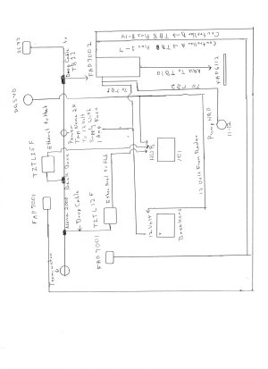
Crude Drawing.jpgI have a rather crude drawing attached. I have read that the SC30 had internal termination; but have not seen the same info for the SC33. The backbone will be powered from the yellow cable that come in the NEMA Starter Kit, off a fused 12 Volt source.

SC33 connected directly to backbone.
TZTLs' connected to backbone and Hub.
Transducer not in drawing, but connected to one TZTL.
One drop cable connected to TB11 on FAP7002
FAP7001s' connected to TB8 pins 1 thru 14.
RRU connected to TB10
PumpHRP11-12 connected to TB2.
12 Volt from Batteries connected thru a breaker to TB1.
Radar connected to 12 Volt thru breaker and Ethernet to Hub.

If the SC33 has internal termination, that should make the TWO terminations that are required. Since the Backbone is getting power from its own source rather than the FAP7002 does it need termination.

Even though it does not show in the crappy drawing the radar, pump and FAP7002 are all on separate circuits, radar and pump and processor on separate breakers and Backbone on a one amp fuse.

Hope I haven't just made it more confusing

Thanks,
Phil
 
I have read that the SC33 had internal termination; but have not seen the same info for the SC33.
That isn't correct. The normal SC33 will have a standard drop without termination. Maybe you saw something from the SC30. There is an OPTIONAL cable for the SC30 that includes an embedded termination but that is for use with the IF-NMEASC interface that turns the SC30 into a AD10/0183 output device. Unless you ordered something off standard, you do not have a termination within the SC33 or it's cable.

Your drawing was great. Reviewing it and your comments; I have a few thoughts for you to review.

FAP7001s' connected to TB8 pins 1 thru 14
Since you are using both bus A & B, jumper J104 on the processor must be set to pins 3&4. Both control buses must be terminated (Not NMEA 2000 but kinda similar). Each display control unit should have the cable which goes to the processor and the other connection at the back should be terminated. This is VERY important and one of the most common installation mistakes.

Currently as drawn, your NMEA 2000 bus only has one termination. You need to add one where it makes sense. Any drop from the bus MUST be no longer than 6 meters.

Your power tee with fuse... Please ensure that it has all wires connected. Some power tees have two sets of wires. Many fail to connect both sets of power wires. For units with two sets: one set of power wires drive power to the left part of the tee and the other set drives right. If both sets not connected, you only have power on half the bus.

Radar connected to 12 Volt thru breaker and Ethernet to Hub.

You show the radar on the drawing as the DRS4D. If it is the DRS4D, power required is 48v and normally powered by the PSU017 or PSU012. If you have the DRS4DNXT solid state, then your good.

I would ensure the power wire gauge, to power the pilot processor, be large enough to carry the current needed. Same from the processor to the pump. The longer the power wire, the larger the gauge wire needed. Small wires are a problem.

12 Volt from Batteries connected thru a breaker to TB1.
Recommended breaker should be 25 to 30 amps.

It is looking really good.
 
The total length of the backbone will be 12 meters with the power tap in the middle. Forward leg will have a two tees and 2 meter drop to TZTL15F and a 6 meter drop cable to TZTL12F and a terminator at the end of the run. Aft leg will have a tee and 6 Meter Cable to the SC33 and a terminator. May add a GP330B on the aft leg in the future, but not really planning on it as the current stuff should be more than enough.

Since I'm using the SC33 for heading data, TB6 is not needed as data should come thru the Canbus?

Both FAP7001s' will have the terminators attatched, and J104 will be changed to pins 3 and 4.

For powering the backbone is TB12 preferred or required, or can power come from a clean 12 volt source (fused of course).

The radar is DRS4D NXT, ethernet and 12 volt thru breaker.

Would be nice if boat builders built them with adding electronics in mind, running wires was a real pain. Feel free to ding me if I am missing something as it has been a long time since I did this type of work. I think we are getting close to finishing this up. :)

Thanks,
Phil
 
Since I'm using the SC33 for heading data, TB6 is not needed as data should come thru the Canbus?

Yes SC33 is NMEA 2000 and the data will be on that bus getting to your pilot on TB11. TB6 is NMEA 0183 a completely different format of data. If you have a good source of 0183 that you want the pilot to have you can use TB6. At this point it doesn't sound like you do.

For powering the backbone is TB12 preferred or required, or can power come from a clean 12 volt source (fused of course).

TB12 is rarely used in most installs. In your case you have a fused Power tee giving power to the bus. You will NOT use TB12. If you do, you will create problems with two sources of power fighting each other.
Would be nice if boat builders built them with adding electronics in mind, running wires was a real pain. Feel free to ding me if I am missing something as it has been a long time since I did this type of work. I think we are getting close to finishing this up. :)
Agreed. It sounds like you are on track to a nice installation. :respect
 
Back
Top