DRS4D-NXT to TZT touch

Jmg132488

New member
Hello all
Just looking for alittle clarity
I have the radar wired on the inside

But wondering if anyone can guide me on the other half of connections

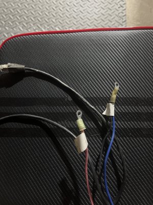
Ethernet goes into the unit

But I also have a red black and blue to connect somewhere

Is it just radar connection
Then opposite end
Rj45 into TzT14
And then putting power and ground to the cables ?

Any help would be appreciated
Thanks all
 

Attachments

  • image.jpg
    image.jpg
    2.5 MB · Views: 9
Section 1.3 of the Installation Manual covers the wiring requirements. Be sure to connect the shield wire as well.
1720529549027.png
 
Yes no need to use nmea2k it’s all done down the net cable
Plug it direct or into a switch
Simpler terms please
So network goes into the screen


I’ve already wired the radar
With the net cable
And the red — blue/black


Other end has same red blue and black
Seems like blue and black are bundled together and red is on its own


I’m plugging the net cable into the display
But just curious what to do with the red & blue/black


Sorry I’ve dealt with other radars but the NXT this is a first
 
I would try to offer some assistance but I am very confused about your question. The DRS4D-NXT has a pre-installed pigtail cable. It has a cannon type plug hanging out. The scanner cable itself has a matching cannon type plug and they just plug together. The other end of the scanner cable as the power wires that go to the power system (two wires) and an RJ45 network connection. The RJ45 connector would normally go to the onboard network hub but in some small installs it might plug in directly to the unit when a hub is not needed. Two power wires and a network cable at the MFD side. Have you done something different like removing the pigtail from the radar dome? If so, why? I am just confused about what you are asking to offer any definite advice.
 
I would try to offer some assistance but I am very confused about your question. The DRS4D-NXT has a pre-installed pigtail cable. It has a cannon type plug hanging out. The scanner cable itself has a matching cannon type plug and they just plug together. The other end of the scanner cable as the power wires that go to the power system (two wires) and an RJ45 network connection. The RJ45 connector would normally go to the onboard network hub but in some small installs it might plug in directly to the unit when a hub is not needed. Two power wires and a network cable at the MFD side. Have you done something different like removing the pigtail from the radar dome? If so, why? I am just confused about what you are asking to offer any definite advice.
Hey Johnny , I didn’t remove anything

So the radar cable looked like this

One end
Network cable & red blue and black
I fed that into the NXT and wired it up
The radar had labels for red blue and black

On the other end it’s virtually the same

A network cable and 3 wires pictured in the thread

For this install the network would go directly into the MFD but was basicly trying to figure out what am I to do with the red blue and black wires on the MFD end of the cable

I belive the cable is original but it is confusing me a bit
 
Did you buy this radar used?
The end you have pictured is the end that goes to the hub/MFD not the dome. What does the other end of the cable look like?
 
Yes used
The other end is virtually the same
Except just raw wires
which I fed into the radar ports labeled
 
You can make it work by taking the raw network wires and wire it up into an RJ45 connector so that it can be inserted into the RTR. The power wires would go into the power connection of the RTR to power it.
 
Back
Top