color codes for PG500 wiring

G

gordwedman

Guest
Hello guys.
I don't see a Tech Tips tab for the PG500 sensor and the manual is no help so I am reduced to asking what the color codes are for the wires coming out of the PG500 power/data cable.
From memory the wires are:

black, obviously ground
red, obviously positive
blue?
green?
white?
yellow?
bare wire, shield?

A somewhat related question: the installation manual for the MFD8/12 shows a diagram of the 18 pin NMEA plug with the pins numbered. I would just like to confirm that the perspective for this diagram is looking at the plug from it's front.

Thanks
Gordon
 
NMEA wiring on almost all Furuno products are shown with color code on page S1 of the Operator's manual (Normally the last or almost last page). The interconnection diagram will show you basic input and output wiring. For the NavNet 3D, you will also find a full breakout of the color code of the 18 pin cable on page 23 of the installation guide. With all Furuno drawings, it is helpful to know some of the abbreviations. Here is the decoder ring.

RD= Receive Data
TD= Transmit Data
SD= Send Data
SG= Signal Ground
A= +
B= -
H= Hot/ +
C= Common/ -

Since you considering a connection of your PG500 to the NN3D system, I would recommend that you read the following post.

viewtopic.php?f=11&t=126
 
Hello Johnny and thanks for the reply.
Before posting my note I did look at page S1 in the MFD8/12 installation manual. This is what it shows for the heading sensor:

ORG/WHT
GRN
GRN/WHT
BLU
BLU/WHT

My experience with electrical wiring suggests that ORG/WHT should be an orange wire with a white stripe. The PG500 power/data cable I purchased from an authorized Furuno dealer does not have such a wire. Nor does it have GRN/WHT or BLU/WHT. In addition it has a Yellow wire which is not mentioned by S1. The colour codes do not match. This is why I posted my query.

Could you please tell me what the use is of each of the wires from the power/data cable:

black
red
blue
green
white
yellow

Thanks
Gordon
 
Gordon

When looking for the PG500 color code information; the best location is the PG500 manual. The interconnection drawing from the MFD manual, which you were referring, is going to cover the color codes for the MFD wiring not the PG500. When you do need the wiring for the MFD, I would recommend using page 23 of the install guide for a better discription of the 18 pin cable.

The interconnection drawing(s) normally require that you to apply the "Decoder Ring" that I gave you. The 18 pin cable wiring is explained a lot better on page 23 (No decoder needed).

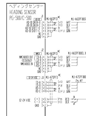
PG500 Interconnection Drawing:
PG500 color code.jpg

Using the PG500 interconnection shown above; you will find the 7-pin power data cable shown at the bottom. For example TD-A (Transmit Data +) is shown as a WHITE wire and the TD-B (Transmit Data -) is shown as a BLUE wire. If these are not already connected to something like our NavPilot; you can use these to wires to take data over to the NN3D MFD. (See the link I previously provided for one example of wiring the PG500 to an MFD)

Every wiring install is different, depending on what port(s) you wish to use on the PG500, or what port(s) you have open on the MFD.

If you get stuck it might be easier to discuss your specific install with one of our techs on the phone. (West Coast 360-834-9300 / East Coast 410-479-4420 )
 
Could you please tell me what the use is of each of the wires from the power/data cable:

black
red
blue
green
white
yellow


black (power Neg)
red (+ DC)
blue (- NMEA out)
green (-NMEA in)
white (+ NMEA out)
yellow (+ NMEA in)
 
Hello Johnny and thanks again.
I had looked in the PG500 manual. I downloaded it to my tablet. When I look at the page you show I only see the blocks and lines on my tablet, no text or other detail. It did not occur to me that this was a problem with my downloaded version. I just downloaded the manual to my computer and I can see the same diagram you provided. I guess I will have to download manuals to my computer first and then copy them onto my tablet. :shock:

I should be able to figure things out now but it would be nice if you had a repository of typical wiring setups similar to what you provided to aquabelle.
cheers,
Gordon
 
Just a update comment on the tablet issue. It didn't occur to me while writing my reply but I also have the MFD8/12 installation manual on my tablet and the S1 wiring diagram shows perfectly so there is something peculiar about the PG-500 manual that my tablet does not like.
 
I personally use the printed manual that comes with unit, when it comes to drawings. When using a digital device, Adobe viewer can have problems on some devices because the font sets. In some cases, you have to load the Japanese font pack/plug-in. A good source of example drawings besides those provided in the NN3D installation guide; are shown under the individual products on the web site. You will normally find the "TECH INFO" tab very useful. The tab will normally offer many interface drawings and example drawings. We are still adding to this on a regular basis. If something isn’t clear feel free to call tech support. We are always happy to hear from our customers.
 
Back
Top