1731 MK3 Dome wires

A

Anonymous

Guest
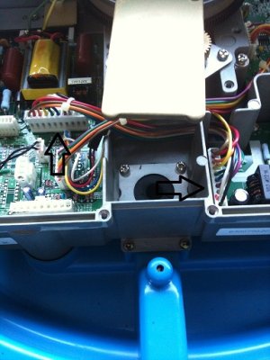
Ok, so this is a little embarrasing but I need some help. I was removing the scanner cable from the dome for re-rigging. I started taking the pins out of the connectors so I could pull the wires back through my T-Top. The rectangle plugs will not pull through obviously. I accidentally pulled the pin connectors out of a plug that was NOT connected to the scanner cable, instead it just looped back and plugged back into the board so I should have left them alone. Well, I want to plug the back in but this plug is not in the manual to show which color wires go in which slot of the plug. I need a schematic to show me which wire goes where! The dome is useless now! Thanks, Chris
 
Chris,
If I understand your question correctly, you are talking about interconnection wiring between the circuit boards that looks similar to your radar cable connectors. (See attached)1731mk2 scanner.jpg

If the one I attached isn't clear enough, you can view it towards the back of the operator's manual on page S-3. Furuno USA sells the pins and the white connectors (via our dealer network) if you need to replace anything. The pins are crimp-on, so you will normally need a pin crimper to put the pins on properly. If that isn't what you needed, let me know.
 
Johnny, thank you very much! I think thats the one. I'll take this schematic back to the dome and look. I dont have the original manual, only the one listed online and it stops at S-1. I will include the link to the one I was looking at online below. Thanks again, I will post my results sir.

http://www.furunousa.com/ProductDocumen ... -17-05.pdf
 
Johnny, I opened the dome up and found that it wasn't the correct diagram. The one I need is the 10 pin connector. I didn't see that diagram in the other manual that you sent either. But, this is what I did. Tell me if this wasn't right, the pin connector on the other end of the harness is numbered 1-10. All I did was use the same numbers to plug the pins into the other ends connector because it is also numbered 1-10. Was I correct in doing this?
Thanks, Chris
 
Let's make sure we get this correct. Please provide the RSB number from the sticker on the dome and the last three digits of the FCCid#. (aka the RTR number) This way we know what scanner you have. The 1731Mk3 should have been the RSB0071-058, which matches the drawing, so we need to dig in a little deeper and find out yours is.
 
My sticker doesn't have an FCC# on it. Ive opened it up and looked for an FCC or an FTR #. Let me post a pic and see if it can be identified that way. Maybe by serial number?
 
Lets see if this works......
Here is a pic of the sticker on the dome. The second pic is of the harness in question indicated by the two arrows. The arrow on the right is the plug I took the wires out of and have since put back. The left arrow is of the other end of the harness which I never disturbed. I guess we have added a new question to the mix, which is.....what dome do I really have? It was hooked to a 1731 MK3 and works just fine but who knows. The second and original question is, the plug that the right side arrow is pointing to is the one I accidentally disconnected the wires from and have since re-installed based on the corresponding numbers on the plug on the other end of these wires marked by the left arrow.........was my educated guess right by thinking both ends of the harness are marked the same on the plugs?

Am I driving you crazy yet? Thanks for hanging in there though.......I really need the help. :furunophoto (3).JPG
 

Attachments

  • photo (4b).jpg
    photo (4b).jpg
    102.5 KB · Views: 2,388
The connection you are looking at is the PTU to the Modulator. It is a 10 pin connection that is exactly as you assumed. It is pin 1 for 1; across the board.
The color code is as follows:
Pin
1 – Brown
2 – Red
3 – Orange
4 – Yellow
5 – Green
6 – Blue
7 – Purple
8 – Gray
9 – White
10 - Black
 
Back
Top