295 with r99 engine interference and troubleshooting steps

  • Thread starter Thread starter teffy
  • Start date Start date
T

teffy

Guest
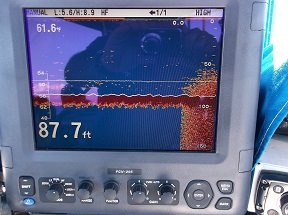
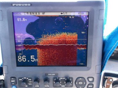
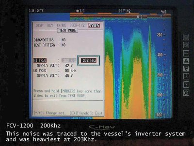
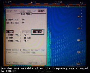
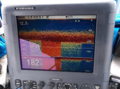
looking at some spots today and shut down the main generator was on. looked at the sounder when i started up and got this image on the sounder. fired up the engine and the noise image in the attached photo starts. u can see a excellent return destroyed by starting the engine and continue as long as the engine is operating.

i just figured this out as i always believed that i had sounder turbulence and accepted it as "it is what it is" and not the engine noise.

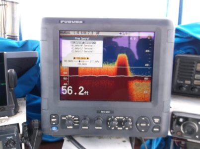
I monkeyed around with low med high interference settings as you can see no difference


the transducer cable run is next to the engine instrumentation cable would this be an issue?
the engine vibrates normally at idle would that affect the transducer?

where would you start to troubleshoot?
 
here turning engine on then off
 

Attachments

  • 31120interference2a.jpg
    31120interference2a.jpg
    409.1 KB · Views: 1,298
Teffy,
Does your engine also have a charging alternator for your batteries? If so, you probably will need to add a filter cap to suppress the noise.

Snips
 
Teffy,
This is the one I like to use.
Google CG153U050W4C, this one was on EBAY.

Snips
 

Attachments

  • Cap.JPG
    Cap.JPG
    22.5 KB · Views: 1,261
Thanks snips!

Would only one suffice on the positive or do i need a negative side one also?
 
Teffy,
This a capacitor, so the negative side goes to ground (most likely the engine block) and the positive side will go to the output on your alternator.

Snips
 
thanks again Snips

Ran again today.

installed a newmar pc25 i had laying around in my boat boxes of wasted boat money. i am awaiting the filter cap you use. Stand alone 12v source independent of all vessel dc. all ok until engine turned on then same condition. interference filters to low medium high no effect. 3 position sensing switch (for manual selection of sensing source) selected to house battery, start battery then alternator off (no sense) no effect.

the xducer cable run is laying under the cummins harness (no splices on harness or cable). which i am assuming is the issue.

i plan on pulling the entire xducer cable out and run on the deck to 295 check results away from any other ac, dc or instrumentation sources.

hopefully this clears the issue

My thinking is to cover the entire cable with 1in tinned copper metal braid sleeving emi/rfi shielding and run it away from the cummins harness while being covered with the shielding . the transducer is directly under the engine.

Thoughts?

Is there a minimum distance from ac or dc cabling i can get away with? or is it trial and error?
 
Teffy,
The interference filter is design to look for patterns so it won't be much help in suppressing the noise that is appearing. In-line DC filters will be of little help also.

From what I have seen rerouting or adding more shielding will be of little benefit.

If this was my boat I would do the following.
1. To make 100% this is alternator related. If your alternator has a field wire you could disconnect that or remove it's drive belt.
2. Add a ground to the sounder case (or remove it).
3. Are all four shield wires on the transducer going to the metal cable clamp? If so, remove them to see what happen to the noise.

Below is a screen shot from a vessel we were on recently that needed a cap. The blue noise is when the cap is disconnected.

Snips
 

Attachments

  • Cap 1.jpg
    Cap 1.jpg
    605.1 KB · Views: 1,581
ran the boat today with the sounder on an independent battery (12v agm). ran cable along deck away from any harnesses or electrical wiring. no capacitor inline.

the deeper i got bottom fuzz returned at around 14kts and remained at that speed with either the house or start battery bank selected. slightly less bottom fuzz with the alternator switched off engine on .
stopped over my test spot in about 90ft of water using 200 mhz.

I determined that with the alternator on either the house or start bank it created significant bottom fuzz. this is with std pulse length and wide beam width selected.

I changed to short1 and narrow beam width to see what would happen and still had the issue.

decided to experment with the frequency. first i moved the frequency down from 200 mhz and the fuzz got worse. decided to go up in freq and the farther from 200mhz the less fuzz interference both with the alternator on and at speed went away.

I am still going to retest after i remount my transducer cable away from any potential sources of interference to verify everything.

can u explain what just happened?
 
here is the pic

you can see going below 200mhz then gradually to 206 mhz
 

Attachments

  • 200to206mhzaaa.jpg
    200to206mhzaaa.jpg
    192.6 KB · Views: 1,540
Teffy,
Most noise is within certain frequency range. Below are a couple of screen shot of noise that was traced to the vessels inverter.

Snips
 

Attachments

  • 200 203 Khz.jpg
    200 203 Khz.jpg
    93.1 KB · Views: 1,536
  • 200 198 Khz.jpg
    200 198 Khz.jpg
    75.8 KB · Views: 1,536
finally got out. realized i needed to be a bit more organized but have some data.
conditions- separate 12v battery, alternator sensing select-able between house or start banks as well as no sensing (off but still rotating).

went thru the above listed tests. the unit case was not grounded previously so i ran some wire from the dc negative bus, and from the engine block itself bypassing the shunt.

i tested with the tranducer cable ground wiring connected to each other with temp pigtail ground wire to the screw on the circuit board ground.

basically no real change until i removed the internal ground and it cleared up but was not perfect. i decided to separate the temp pigtail from the main transducer cable grounds. cleared up still not perfect. then i attached the wire i ran from the engine block to the case ground and it cleared up perfectly.

see the photo
 
no offense i took your advice as basically start trying every combo you can imagine so here is what i ended up with

u will see no internal cable ground case grounded to engine block, then no internal cable ground no case ground to engine block, then dc neg bus bar to case ground, then no internal cable ground no case ground to eng block, then no internal cable ground to case grounded to eng block.

I still am going to try the filter cap as the alternator is still making a bit of noise.

im scratching my head as to why the noise is present with a separate battery.
 

Attachments

  • nointgnd,dcnegnointgndeng gnd1.jpg
    nointgnd,dcnegnointgndeng gnd1.jpg
    280.5 KB · Views: 1,407
Teffy,
Good for you for taking the time to systematically go through all the different combinations.
I have been there and know how frustrating it can be, but on the other hand you can feel good knowing you now have a very clean picture.

Snips
 
Back
Top