NAVpilot-511 Clutch/Brake

I'm just about finished with the install of my NAVpilot -511, FAP-5002, running the dockside checklist and I'm getting a Disconnect B/C (clutch/brake circuit not getting power). I have no idea what the Clutch/Brake is, though I can see where it would attach on the circuit board). I'm running to an old Wagner hydraulic steering system, which is running fine when manually powered. My older system was a Wood Freeman.
I am using the FAP6111 Rudder Reference Unit and am getting good feedback from that on the controller. When I touch the port and starboard turn arrows the wheel starts to turn in the right direction then stops and gives me the code.
Please advise, whoever you are. And thanks in advance. I hope I have been clear.
 
Are you connecting the MOTOR + and MOTOR - outputs from the FAP5002 to a reversing hydraulic motor?
Verifying that nothing is connected to the B/C connector on the FAP5002?
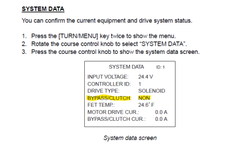
Bypass/Clutch is only used if a pilot valve needs to be repositioned when the AP is engaged or some sort of relay needs activated for the Ap to take command.
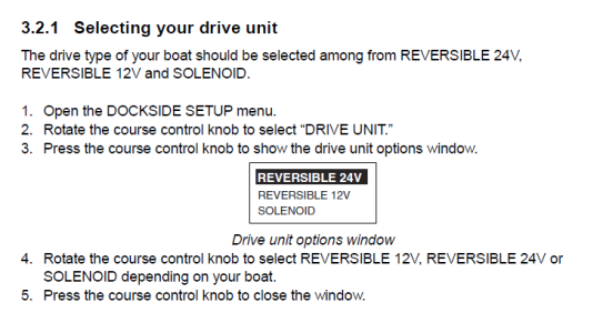
If there is no B/C requirement, make sure the pump is set to Rev. 12V or 24V (the applied voltage to the FAP5002 Mains)

1733175104800.png
 
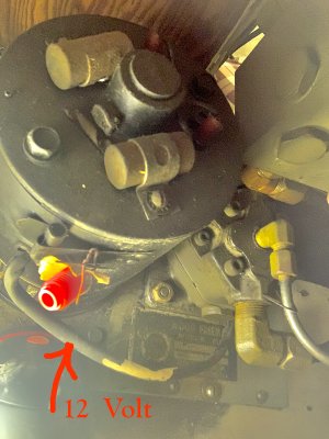
Thank you for your reply. There is nothing connected to the bc connector on the processor. I have the drive unit set to solenoid. When I had it set to reversible 12v, it would trip the 15 amp breaker, which is the same breaker the motor ran on with the Wood Freeman system. I can't say for certain that it is not a reversing motor. There were three wires running from the motor, including the ground. I can check the documentation again. I have the controller plugged into the TB9 slot on the board.
 
Last edited:
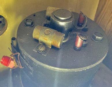
A 3-wire connection is used for SOLENOID control. A common ground to both solenoids, a wire to the port solenoid, and a wire to the starboard solenoid.
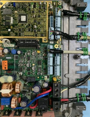
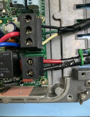
Can you get a picture of the wires connected to the FAP5002 TB2 connections labeled SOL A, SOL B, and GND. Also, a picture of where the wires are connected to the solenoids.
 
We need to reset this and set it back up. The only time the system should show "EXISTS" is when a current draw is detected on the BC connector, of course with nothing connected there this is a false indication.

To reset:
Get pictures of the SHIP'S CHARACTERISTICS, DOCKSIDE, and SEA TRIAL menus to speed up the setup after the reset.
 
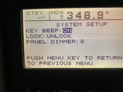
Following your instructions: There is no second page, or option to clear. ... so, stopped in my tracks for now.
 

Attachments

  • System Setup.jpg
    System Setup.jpg
    705.2 KB · Views: 0
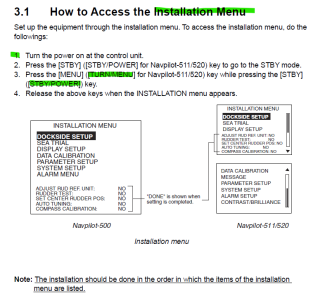
No biggie, it is not in Installation Mode. Here is how to get into installation mode:
Once in Installation mode go down to SYSTEM SETUP in the menu and then you'll have the second page option where the MEMORY CLEAR option is.
1733505683288.png
 
Well. Progress is being made. I was able access the appropriate menus. Now I find that I am failing the "rudder test." The wheel does go back and forth several times. I start the test with the helm at approximate center. It is 16 spokes from lock to lock and I start the test at the middle spoke. Did the test several times and got the same result. I have the INSTALLATION MANUAL, and I'm going through the steps, one by one..
UPDATE: I Deleted the processor data and redid the set up and rudder test which showed the clutch by pass as EXISTS and a message to disconnect. Perhaps I need to delete the display data again. and redo the set up. At least I am becoming familiar with the screens and menus.
UPDATE#2. Deleted data on processor and display. Rudder test proceeds with helm going back and forth from port to starboard, until a message come up to DISCONNECT B/C at which point the helm turns in one direction only without stopping and the display shows B/C : EXISTS. I think I am stumped again and hope you can give more good advice.
 
Last edited:
Back
Top