Linking VX1 to an auto pilot

A

Anonymous

Guest
I have a VX1 RDP-139 that I want to link to my new auto pilot. The autopilot has 2 wires a GPS + and - wires. I was hoping to get this info off the VX1 Data port 2 with a 6pin wire, but though further research I belive this has to come off a differant port. Right now Data port 2 and 4 are open, please tell me one of these will work? I have the unit hooked to a 6kw radar, a GPS sensor,Sounder module, and have the compass on it.
IF I can use 2 or 4 please include the info on which wire I will need and or which pin and how to figure out which pin is which to get this GPS data from/to. I currently have a 6 pin Furuno wire MJ-A6SPF0014-050 19S1015-0, if this wire is any help that would be great, as I already own it.

Thank you and such a great forum full of info and sharing people. I have realized this unit is very capable but also requires alot of knowledge and need to be a tech junkie to make it all do what I want.
Kevin
 
The autopilot has 2 wires a GPS + and - wires. I was hoping to get this info off the VX1 Data port 2 with a 6pin wire, but though further research I believe this has to come off a different port. Right now Data port 2 and 4 are open, please tell me one of these will work?

Data 2 on the RDP139 is normally the preferred port to drive the auto pilot (using 6 pin NMEA cable 000-154-054..... White + and Black -)

I currently have a 6 pin Furuno wire MJ-A6SPF0014-050 19S1015-0, if this wire is any help that would be great, as I already own it.

I am not where I can cross reference the part number you have but if the cable isn't BLUE, then it should work fine.

Welcome to the Forum
 
Johnny, thank you very much for the reply. Exactly the info I was looking for. No need to cross reference as the cable is blue, so now to go find the right cable.
Thank you.
Kevin
 
The blue cable would be a network cable (crossover) but you could make it work if you ohm it out and ensure you use the correct wires. You would need to take pin 1 (+) and Pin 2 (-) to drive data to the auto pilot.
 
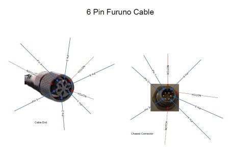
How do you determine which pin is number 1? I hear it is next to some pin, or something like that. Also is pin 1 determined looking at the back of the unit so you have to cross it over to the female connector, or do you identify it on the cable?
 
Johnny, thank you so much for the info.

Using the blue cable listed above I got out the ohm meter and here is what I found

1 = Blue
2 = White
3 = Black
4 = Brown
5 = nothing, maybe the foil wrap around the wires
6 = Bare wire

Obvously I need the blue and white wires for my connection, but maybe this can help someone else.

Thank you
 
A cut blue cable would match yours if they pick the correct end of the cable.
Being that it is a cross over cable and you don't know where the wires cross; a meter is the only way to know for sure. Thanks for sharing the pin-out.
 
Good to know that if you use my chart above you have a 50% chance of being right, and well that means you will be wrong 80% of the time, atleast for me I would be.

Thank you for your help.
 
Would these same pins and application work for a vx2 or is it different? If it is different which pins would I use and do you have a similar picture like above for reference of where the pins are located?
 
So than same cable and same installation of wiring terminals 1 and 2?
 
Back
Top