FCV 588 / Airmar B260

Mim

New member
Hi there. My first post all the way from down under! Great forum. I have bought a second hand boat that came with a Navman 8120 combo hooked up to an Airmar 1kw through hull transducer (B260). I was not happy with the sonar performance of the unit and upgraded to a Furuno FCV-588. I purchased an Air 033-333 connector so I could change the existing Navman connector to the 10 pin Furuno. I cut off the existing connector and spliced in the new Furuno connector by joining each colored wire together ensuring the shielding was how it should be. I selected the 526TID-HDD 1kW transducer in the menu and all seems to be working well. I am still working my way through all the settings etc but just wanted to get some confirmation that what I have done is all ‘ridgey didge’ which is Aussie for ‘ok’! :)
I am certainly seeing depth and temperature for example but am needing to work my way through the settings as the echoes seem to be a little harsh and jagged. I believe I should be able to access enhanced Rezboost and maybe even bottom discrimination?
Appreciate any feedback anyone can provide.
 
Mim,
Welcome to the forum. If your targets look jagged I would be curious what your screen advance rate is? Depending on what you are looking at anything above 1/1 can make targets look jagged. Do you have any screen shots that you could post for us? Also one way to better learn how different settings (gain, clutter, TVG, screen advance) can affect the targets you are seeing is by using the 588's demo mode. 15-20 minutes using the demo mode is easily worth 10 hours on the water.

Snips
 
Hi Snips and thanks for the welcome and quick reply. Advance rate was 1/1 and have changed to 1/2. I have also switched on smoothing. It is difficult to determine what impact this has had as the boat sits in dry dock set up so will do some more playing next time I am out in the boat, including your good suggestion of playing with the demo mode.
I guess my overarching priority at the moment is get some feedback if splicing the new connector in by joining all like coloured wires was the right thing to do. If so, it will make my trials and learnings more satisfying.
Again, many thanks for the quick response. Much appreciated.
ps. Will take some screen shots when I am out there and see if I can post them.
 
Mim,
When you change the screen advance from 1/1 to 1/2 your targets are going to be half the length. If you go the other way 2/1 they will start being more jagged.

Snips
 
Hi Snips et al. I have been reading with fascination some of the posts here and came across this one...
“You can splice it on color for color, and it will work great with the Rezboost capability for the FCV588, including Accufish/Bottom Discrimination. No matching box will be required.

Airmar used to keep the wires independent and then for Garmin tie the grounds together at the connector. The "tie" would be cut off when you remove the Garmin connector.

It looks like they have changed the wiring a bit over the years, so I would recommend the following:

10Pin ----- Transducer
WHITE ---- WHITE
BLUE ----- BLUE
BLACK --- BLACK
BROWN --- Bare shields

Do not connect the orange wire from the transducer at all. :noway”

Which is answering the question I had. However, I believe we connected the orange wires as well when we did the splicing. Can you tell me what the orange wire does and why you shouldn’t connect them?
And it would have been nice to know of the existence of the Airmar splicing box before we soldered all those wires. :-(
 
Mim,
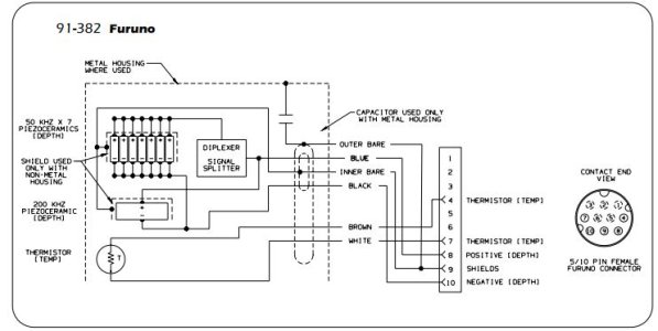
Below is the wiring diagram for the transducer. Basically the Blue/Black/Shield is for the transducer elements and the White/Brown is for the temp sensor. All though this diagram doesn't show it the orange wire is for the TID (Transducer Identification).

Snips
 

Attachments

  • Ducer.JPG
    Ducer.JPG
    50.5 KB · Views: 3,821
Thanks Snip. So is there any problem if the orange wires are connected? Would it impact the functioning of the unit?
 
Mim,
Unless it is wired incorrectly the Orange wire won't change anything. I would leave it disconnected and select the transducer via the menu.

Snips
 
Thanks Snips, It is currently connected so will leave as is for now and try ‘playing’ with settings next time I am out in the boat. Thanks again for all your prompt replies. Much appreciated.
 
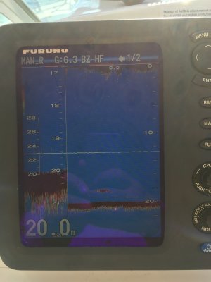
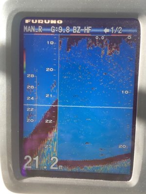
Hi Snips. I am going to try and attach a screen shot. I am not sure why my bottom is showing as a relatively thin line and not covering all of the bottom part of the screen as seems to be the norm in many other shots I see. Any thoughts? Also looking at the screen is there anything that stands out for you that might need adjusting? Again, really appreciate your insights and words of wisdom.
 

Attachments

  • BCAED71C-A169-49D0-BF3E-ECA4B57888BB.jpeg
    BCAED71C-A169-49D0-BF3E-ECA4B57888BB.jpeg
    575.6 KB · Views: 3,752
Mim,
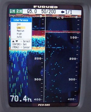
Those screen shots look pretty normal to me. Depending on the transducer the 200Khz side can have a much narrower (thinner) bottom return than 50Khz. This because the beam width of 200Khz is about a third of 50Khz. Below is how the 200Khz compares to the 50Khz using a B-260 transducer in roughly the same water depth. If you look closely you will notice that the thickness of the 50Khz bottom return is close to three times that of the 200Khz. That is because the beam width of the 50Khz is 19 degrees vs 6 degrees of the 200Khz side. If you are using a 600 watt transducer the BW can be closer to 12 and 42 degrees respectively.

Snips
 

Attachments

  • 585.JPG
    585.JPG
    64.2 KB · Views: 725
Back
Top