You are using an out of date browser. It may not display this or other websites correctly.
You should upgrade or use an alternative browser.
You should upgrade or use an alternative browser.
Furuno 1731 Mark III
- Thread starter H2obio
- Start date

You would want to look in the manual (posted at the product support page here: https://www.furunousa.com/en/support/1731MK3) and page S-1 shows the full interconnection wiring wire for wire.
Thanks! I'll take a look.You would want to look in the manual (posted at the product support page here: https://www.furunousa.com/en/support/1731MK3) and page S-1 shows the full interconnection wiring wire for wire.
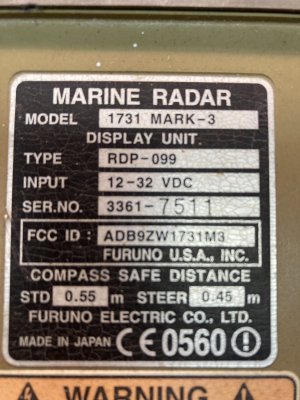
Greetings? Question for Mr. Electron - I will be working on a boat this summer with a Furuno 1731 Mark 3 that has no image on screen. Button pushes yield beeping noise, but screen blank. Can you point me to a manual somewhere for this unit? And can you steer me toward how old it is with serial number - 3361-7407?
** Never mind. Didn't fully read the above post. found the manual !!! Still would like to know the age and life expectancy if possible !!! ***
Thanks a ton !!!!
WC
** Never mind. Didn't fully read the above post. found the manual !!! Still would like to know the age and life expectancy if possible !!! ***
Thanks a ton !!!!
WC
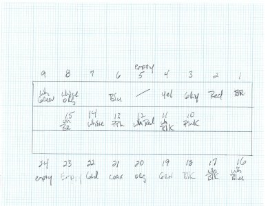
Well, I thought I was pretty good at deciphering schematics, but this one's got me beat. There are 18 wires and 24 slots in the antenna plug, which are numbered (tiny). The challenge is the schematic seems to state that two wires go in same numbered slot which doesn't appear possible...........any help out there?
Thanks, Ron
Thanks, Ron
Which two wires are you speaking of?

Depends if you are talking about the radar side or the display side. White wire with orange tracer (B=Big gauge) goes to pin 8 at the display side but at the radar scanner it goes into pin 1 of J801 of the VH-9 molex connector.
There are three connectors in the scanner. You have more than one pin one. White goes to pin one of J802.
Green goes on Pin one of J611 (which is a completely different connector.
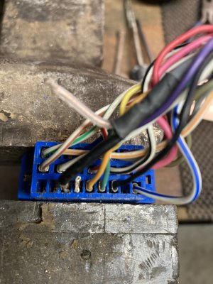
Ok, the connector I have on the antenna side has 9 pins on each side and six in the center. I went with the number to color correlation that I believed to be correct, but the schematic asks for two white/blk (B) for pins17 and 11 respectively, but I only have one wire of that color. Attached is the way I put it together; hope it makes sense!
Attachments
If you have a 1731Mk2 there will be three molex connections in the scanner from the scanner cable. a 9-pin, a 4-pin and a 13-pin as shown in the interconnection diagram from the manual. When talking about the 9 pin, it is this part of the drawing.

Ultimately if a prior owner used the wrong type of cable stock and the wires are not the correct color it won't matter as long as you ensure that the wire leaving the display gets to the correct destination. This can be confirmed pretty easy with a multi-meter. It is important that the pin numbers at the display get to the appropriate pin in the scanner based on that diagram from the manual.
Ultimately if a prior owner used the wrong type of cable stock and the wires are not the correct color it won't matter as long as you ensure that the wire leaving the display gets to the correct destination. This can be confirmed pretty easy with a multi-meter. It is important that the pin numbers at the display get to the appropriate pin in the scanner based on that diagram from the manual.
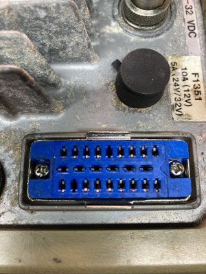
The 1731MK3 has three molex connectors at the scanner side and one 24 pin connection at the display side as shown in wiring diagram. If you have a 24 pin at the scanner then that scanner doesn't belong to that 1731Mk3 display.

Thanks again. Here's a pic of the plate off the scanner/antenna. Both units have one 24 pin molex. It seems unlikely that someone would rewire it to fit, but I suppose anything is possible. Both these units were on my buddies whaler for many years and worked flawlessly together. I did remove the molex from the back of the display with the hope that I could just copy the wiring to the antenna, but the colors are all different.
Attachments
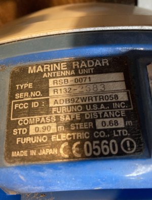
The combination of the RSB0071 and the RTR of 058 on the radome narrows the possibilities, but can you also provide the RDP number from the back of the display that is connected? This will help us pinpoint the radar model number.

That RTR number (RSB0071-058) is the correct unit for the 1731Mk3. That said these photos you provided can't be of a connector at the radar (dome) scanner. Again the dome has three connections (white molex connectors). Are you not seeing these connectors inside the dome connected to the boards?

Similar threads
- Replies
- 4
- Views
- 534
- Replies
- 1
- Views
- 1K
M