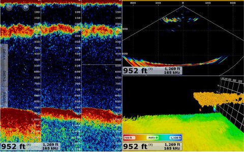
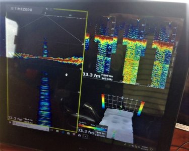
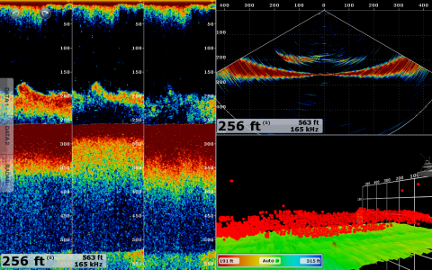
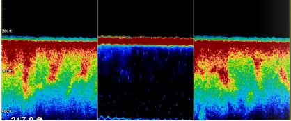
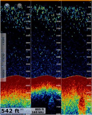
Hey gang, i was playing around in 100 ft of water and TVG setting. I noticed when I increased the numerical value to like 7 or 8 the picture showed me better detail. When I had it 0 my gain was at 80 and my returns were ok. Now that I have changed it and lowered the gain to 70 my screen is much better. There is a TVG depth also in the Dff3d menu when actioning the settings. Do i need to adjust that in addition to the TVG and Gain settings? just trying to understand the TVG better
You are using an out of date browser. It may not display this or other websites correctly.
You should upgrade or use an alternative browser.
You should upgrade or use an alternative browser.
TVG setting/Tzt
- Thread starter MikeR13
- Start date
MikeR13,
Thank you for your inquiry.
TVG stands for Time Varied Gain. In plain terms; we can apply varying amounts of gain (sensitivity) to the returned targets at different distances away from the transducer. Without this ability returned targets that are closer to the point of signal origin (the transducer) would appear larger that those targets further away from the transducer even if BOTH targets were exactly the same sized. You've taken an excellent step toward understanding the effect that adjusting the TVG can have on your target returns. My suggestion would be to continue down this path and make adjustment based on the particular fishing conditions of that particular day.
Good morning MikeR13,
Thank you for your inquiry. We are happy to hear that you are experimenting with some of the other settings in the TZT and the fish finder. It sounds like you are running a TZT system with a DFF3 network fishfinder.
To follow up on your question below, there are a couple ways to look at TVG. In real simple terms with the DFF3 when you turn up the TVG you will see more on your screen. The lower the TVG Level the less you will see on your screen. We like to say with the DFF3 and respect to TVG: More is More and Less is Less.
So what is TVG: well it stands for Time Varied Gain. Meaning the more you increase this value the gain will get stronger by time which is also another metric for distance with a fishfinder. Another way to look at it would be from the surface of the water and the bottom. TVG will increase the gain of the fishfinder as it gets deeper.
So why would you use this feature? It is a way to decrease the amount of clutter in the water column without decreasing the overall sensitivity of the sounder when searching for fish at the bottom or deeper depths. Traditionally without TVG to decrease the clutter on the screen you would either have to lower the gain or increase the clutter control. But with TVG you can tell the fishfinder to maximize the gain and deeper depths so it may give you less sensitivity at the surface but increased sensitivity down deeper where the fish are.
The TVG settings with the DFF3 also use TVG distance along with TVG Level. Again the level will control the sensitivity of the TVG: More is More, Less is Less. But the distance control will allow you to set the distance you want the gain to be maximized at. So if you are fishing in 600ft of water and you set the TVG Distance to 600 feet, the TVG level that you choose will be maximized at 600ft, the shallower you go the less sensitivity you will have. So you have to be careful to pay attention to the TVG distance, for example. Say you set your TVG level to 8 and you set the TVG distance to 600ft. But lets say you are only fishing in 300ft of water. With this combination your TVG Gain Level would not be maximized until 600 ft which is deeper than what you are fishing in. So with this combination you would never see your gain maximized so you fishfinder would not be optimized.
Im using the Tzt2/Tzt and the Dff3D. The TVG settings on that unit are available from 0-9 and when I'm at 0 I can basically turn the gain to full with hardly any clutter on the screen. When i put at 8 and say turn the gain to 75 it becomes more cluttered. I can definitely see the returns much better at a Higher TVG. Im not fishing in overly deep water 100ft but with a higher TVG the returns are much better on both the side scan and tri beam. Thanks for you input!! just trying to learn all these features!
intrepid26
New member
C-Bass":1iz64i9f said:Good morning MikeR13,
Thank you for your inquiry. We are happy to hear that you are experimenting with some of the other settings in the TZT and the fish finder. It sounds like you are running a TZT system with a DFF3 network fishfinder.
To follow up on your question below, there are a couple ways to look at TVG. In real simple terms with the DFF3 when you turn up the TVG you will see more on your screen. The lower the TVG Level the less you will see on your screen. We like to say with the DFF3 and respect to TVG: More is More and Less is Less.
So what is TVG: well it stands for Time Varied Gain. Meaning the more you increase this value the gain will get stronger by time which is also another metric for distance with a fishfinder. Another way to look at it would be from the surface of the water and the bottom. TVG will increase the gain of the fishfinder as it gets deeper.
So why would you use this feature? It is a way to decrease the amount of clutter in the water column without decreasing the overall sensitivity of the sounder when searching for fish at the bottom or deeper depths. Traditionally without TVG to decrease the clutter on the screen you would either have to lower the gain or increase the clutter control. But with TVG you can tell the fishfinder to maximize the gain and deeper depths so it may give you less sensitivity at the surface but increased sensitivity down deeper where the fish are.
The TVG settings with the DFF3 also use TVG distance along with TVG Level. Again the level will control the sensitivity of the TVG: More is More, Less is Less. But the distance control will allow you to set the distance you want the gain to be maximized at. So if you are fishing in 600ft of water and you set the TVG Distance to 600 feet, the TVG level that you choose will be maximized at 600ft, the shallower you go the less sensitivity you will have. So you have to be careful to pay attention to the TVG distance, for example. Say you set your TVG level to 8 and you set the TVG distance to 600ft. But lets say you are only fishing in 300ft of water. With this combination your TVG Gain Level would not be maximized until 600 ft which is deeper than what you are fishing in. So with this combination you would never see your gain maximized so you fishfinder would not be optimized.
Hi C-Bass,
I've been experimenting a bit with my fairly "new to me" TZT14/DFF3/82b-35r set up, mainly game fishing in deeper water from 200 - 800m.. I had a conversation with a friend who is very familiar with the fcv295 unit and he was mentioning setting TVG distance. On my unit there only seems to be one setting for TVG which is a sliding scale from 0-9? In the above post it is mentioned for the DFF3 unit but I cant find it anywhere? Am I missing something?
intrepid26
New member
Thanks C-Bass,
Is there a specific depth value associated with each TVG level from 1-9?
It would be a nice feature to have on the DFF3, any chance of it being included in future updates?
Is there a specific depth value associated with each TVG level from 1-9?
It would be a nice feature to have on the DFF3, any chance of it being included in future updates?
Bringing this back up since I have a TVG question regarding the DFF3D. Since you can adjust the Level and the Distance (referring to the multi-sounder mode), seems like I really should play around much more with these settings. Especially at shallower depths.
With my setup there is always more clutter in the center beam, and I think this is pretty typical. Also, I'm thinking that I should experiment more with narrow beams and the single beam mode for bottom detection. Follow your recommendation to start narrow, then go wider.
The deepest I'm typically fishing is 250-350 feet and most of the time in 100 feet or less. So my question is if it's best to keep the clutter setting low or at zero and use TVG to make adjustments to reduce clutter? For example, if I'm fishing in 200 feet I should set the TVG distance to 200 feet and then adjust the TVG level to reduce clutter?
S
Snips
Guest
Marmax,
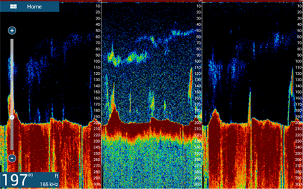
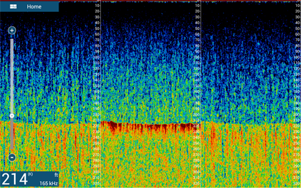
If your center beam is showing more speckle than the outside beams then you probably have some noise getting into your system (check grounding). Yes you can adjust the TVG controls but you are also affecting all the beams equally when you do this. If you have noise you can confirm this by looking at the sonar (cross section) view, just turn up the gain to see it. On the clean system all three beams (see below) should show an equal amount of speckle.
Snips
Attachments
Snips,
Thank you for the reply. I never thought of this as a noise or grounding problem. I'll need your help to figure this out since I'm extremely meticulous with the installation of electronics and wiring.
My signature lists the gear installed and I'm usually running everything except the internal sounder of the TZT2. I run the DFF1 instead and have it connected to a B117 transducer. The DFF3D transducer is transom mounted. The DFF3D is installed exactly as shown in the installation manual.
The only thing I don't have on my boat is a "ships ground", so I've never connected any of my devices with a ships ground. Everything is grounded using the power cable negative. I could connect all the -12V to the ships ground lug on all the equipment but this technically should not be necessary. Even if I created a ships ground it would be the same potential as the -12V buss and seems pointless on my vessel.
As for a noise problem, I'd like more on your thoughts since all my gear is Furuno other than the radio. My F150 Yamaha's are original Parker factory rigged and all I've done is utilize the accessory charge lead to charge my house battery. Perhaps you can add more to the explanation of more speckle in the center vs. the sides to help me troubleshoot.
Here is a multi-beam screen shot FYI. This is very typical for me with some speckle in the center and clean on the sides.

S
Snips
Guest
MarMax,
Multibeam systems are more sensitive to noise than a regular sounder. We have seen this also with the WASSP. Noise comes in on all the channels (8 for DFF3D and 26 for WASSP) at the same time and due to how it is processed appears as "center channel" noise/interference. To confirm this you can view the cross sectional view (see below). So what to do? First is to double check that the foil shield on the transducer cable has a good connection to the metal clamping bar on the case. Second is that there is a grounding stud of the DFF3D itself. This is meant to go to the vessel bonding system. On most vessels the bonding system is separate from the DC negative of the battery. You can try connecting it to the DC ground to see if it helps, however it may make it worse.
Snips
Attachments
Snips,
Thanks for the further clarification. I was unsure before what you meant about interference in the cross-section view. With the latest photo I see exactly what you mean.
My cross-section (unfortunately I don't have any screen shots) is pristine, as in clear and clean in all channels and always has been. Even when messing around with gain and other settings I've never seen noise in the center of the cross-section. It's only the multi-beam center that has more speckle than the sides. Not sure what this means but hopefully it gives you more information to assist.
I have been running my TX Pulse at Short1 and Short2 since I'm not in deep water. This was per discussions with Furuno's SteveB. And I've adjusted the Sound Speed Correction a little.
Next time I'm out I"ll take some screen shots with all three views together so you can see what I mean. It may be a couple weeks though. In the mean time I'll re-check the cable shield ground on the DFF3D.
I'll also check the bonding to confirm what I remember. I've never used shore power on the water and likely will never do so, but I'm always plugged in at home in the garage. I do have a grounding plate that is correctly wired but I'll need to get out the ohm meter and check things to confirm since it's been while.
S
Snips
Guest
Marmax,
In all the reported cases of center channel noise I have never not seen it not appear in the cross sectional view. You may need to turn off all the filters, 100 gain and deep range scale to see it however. You can also see in your screen shot that the center channel speckle has a slight pattern to it which is a indication of it being electrically induced.
Snips
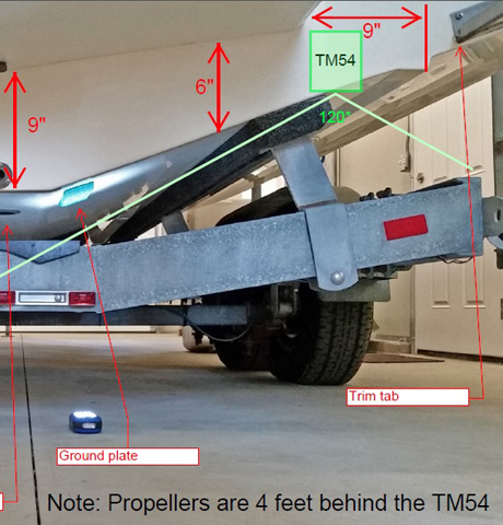
Can't thank you enough for a Saturday response. The more I can figure out before the next time out the better. My grounding plate is just forward and slightly lower than the transom mounted TM54. See the picture. Not that this means anything but figured it's good for you to know. Other than checking the DFF3D grounding shield I can't think of anything else that would cause noise. Could it be propeller noise?

S
Snips
Guest
Marmax,
Could it be prop noise? Sure, but that would be pretty easy to see come and go. Your transducer is not mounted in the ideal location, by mounting so far outboard its going to be prone to turbulence (which I can see in your screen shot).
Snips
Could it be prop noise? Sure, but that would be pretty easy to see come and go. Your transducer is not mounted in the ideal location, by mounting so far outboard its going to be prone to turbulence (which I can see in your screen shot).
Snips
Snips, just to be sure let me know if I'm correct on what you are calling turbulence in the screen shot.
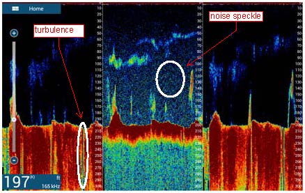
Now here is a screen shot going 20 kts which is clearly a mess. But up to about 20 knots the DFF3D still seems to hold the bottom well. If I'm travelling 10 knots or less and not doing hard turns or stopping suddenly or backing up, I rarely get any turbulence, just the center channel speckle.
[
I'm not concerned about the DFF3D above 10 knots since my DFF1 with the B117 can track cleanly in fishing mode up to 25 knots. Granted the B117 is a very low end (high Q) transducer, but it performs extremely well at speed and covers a lot of area with the LF 45 degree beam. Once I see something on it I slow down and use the DFF3D.
Thanks again for the feedback and I'll be doing some testing with the ohm meter today to see how the grounding system is connected.

Now here is a screen shot going 20 kts which is clearly a mess. But up to about 20 knots the DFF3D still seems to hold the bottom well. If I'm travelling 10 knots or less and not doing hard turns or stopping suddenly or backing up, I rarely get any turbulence, just the center channel speckle.
[

I'm not concerned about the DFF3D above 10 knots since my DFF1 with the B117 can track cleanly in fishing mode up to 25 knots. Granted the B117 is a very low end (high Q) transducer, but it performs extremely well at speed and covers a lot of area with the LF 45 degree beam. Once I see something on it I slow down and use the DFF3D.
Thanks again for the feedback and I'll be doing some testing with the ohm meter today to see how the grounding system is connected.
S
Snips
Guest
Marmax,
You have more turbulence than you think you have. A installation with smooth water flow will yield a bottom return that shows very little variance. Turbulence doesn't discriminate as it affects both the bottom and fish returns.
Snips
You have more turbulence than you think you have. A installation with smooth water flow will yield a bottom return that shows very little variance. Turbulence doesn't discriminate as it affects both the bottom and fish returns.
Snips
Attachments
**Edited to add that things I will try on the water tomorrow to see if the problem gets worse, stays the same or goes away:
1st - connect the DFF3D ships (earth) ground lug to -12V
2nd - disconnect the -12V system from ships ground and try both disconnected and connected DFF3D to ships ground**
Just finished checking the ships ground system and it's as I had anticipated. The grounding plate is only connected to two (2) locations. First is the AC (shore power) GREEN wire and second is the 12V negative (BLACK) at the main batteries. Which of course means it's connected to the House battery negative as well. This is factory original from Parker.
I checked the DFF3D transducer cable and confirmed the shield was adequately connected using an ohm meter between the shield and metal tab. Reading was 0.2 ohms on the 200 ohm (lowest) scale. This is the same reading I get when connecting the test leads together. On any higher scale this reads as ZERO ohms.
The DFF3D transducer cable shield ground bus is "ships ground" which I confirmed via the back lug with the wingnut. Noting again that I do not have any of my electronic devices connected to ships ground, other than the Parker factory connection between ships ground and the -12V DC. Seems to me that the transducer cable shield is "open" as presently connected, that is, any noise on the shield is not being grounded unless there is some internal circuit design that interconnects the two.
An interesting side note is that when checking the resistance across ships ground and -12V ground I measured about 2.6 ohms for the autopilot and radar power supply, yet both the DFF1 and DFF3D measured open.
Regarding the 197 ft depth screen shot and turbulence, are you are referring to the variation in bottom depth? I'm on the South Bank passing over several rocky high spots, so there should not be a smooth bottom. I would like to know more detail regarding the particulars of "turbulence" as you see it in the shot. Thank you.
S
Snips
Guest
Similar threads
- Replies
- 1
- Views
- 73
- Replies
- 9
- Views
- 1K
- Replies
- 5
- Views
- 700
- Replies
- 12
- Views
- 1K


