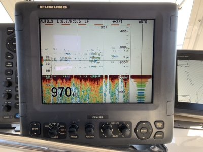
FCV295 w/ Airman CA50/200TID-R99

BadDonkey101

New member
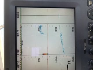
As the subject indicates I have the FCV295 with a 2KW Airman CA50/200TID-R99 transducer. The transducer is through hull mounted in a high speed faring. Recently I’ve started deep dropping for swords but the resolution on my sonar seems very weak beyond 600 feet. I verified my TAP settings and tuned my TVL depth and level and tried some recommended settings for deep water I found in the forum but the best I can get is a thin line and no depth reading. Am I expecting too much from this combination or missing some tuning trick?
 

Attachments

  • AAAC6AED-B22F-42E0-A5B0-4DC8FD0A048D.jpeg
    AAAC6AED-B22F-42E0-A5B0-4DC8FD0A048D.jpeg
    19.1 KB · Views: 1,017
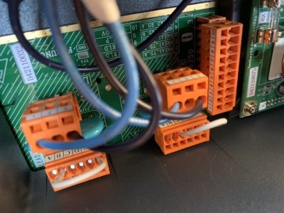
Can you provide a photo of the orange connector where the transducer high and low frequencies are terminated.

Please try to provide a photo that shows the wire colors clearly in the numbered connector.

C-Bass
 
This photo was taken prior to changing the TAP settings. I was advised to set low to C and high to B but I did not change the colored input wire configuration.
 

Attachments

  • 66666A3C-588B-474C-AB21-5639E96BFC97.jpeg
    66666A3C-588B-474C-AB21-5639E96BFC97.jpeg
    113.3 KB · Views: 1,008
I cant tell from the picture, what frequency are the Blue/White and Black/White wires going to?

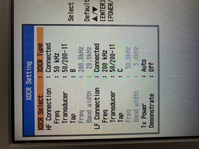
Can also provide a photo of the transducer setup page?

To access, turn the unit off. When turning it back on push and hold the menu bottom down until the transducer setup mode displayed.
 
I’ll have to pull the back plate when I get home this weekend and try to get some better pics. A bit cramped trying to get in behind the unit. XDCR settings are attached.
 

Attachments

  • 6A8B74CC-03D7-4744-950A-44964755CFA2.jpeg
    6A8B74CC-03D7-4744-950A-44964755CFA2.jpeg
    93.5 KB · Views: 1,006
Thank you for the photo,

Ok we need to confirm the wires.

HF Wire Colors 200kHz
Blue: Positive, HF Terminal Pin 3
Black: Negative, HF Terminal Pin 1

LF Wire Colors 50kHz
Blue/White, LF Terminal Pin 3
Black/White, LF Terminal Pin 1

If the wire colors are correct like the above explanation. Your transducer Menu Settings are currently not correct. The CA50/200-1T is a 1kw Furuno Transducer and not the same as the Airmar R99. You also have the HF Channel currently transmitting at 50khz and the LF Channel transmitting at 200khz.

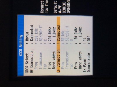
Please set up the menu settings like the photo below for the R99 Transducer. Also the tap settings for the Orange Tap Connectors should be set for the following for the Airmar R99

HF: Tap B
LF: Tap C

FCV295 and Airmar R99.jpg
 
Thanks for the information! I’ll work on it this weekend but won’t get a chance to try it out for awhile.

Greatly appreciated.
 
Got it working! Thanks for the information on the wiring; there were no white stripes on any of the wires so I had to back track the wiring harness to figure out which wires were which. The HF/LF were going to the correct pads but the positive and negative wires were reversed. The XDCR configuration was confusing at first because it didn’t show the R99 transducer as an option but then I went back to your message and realized I needed to set it up as the 1T. The TAP settings were also confusing since the XDCR screen reads opposite of the TAP settings you provided but then I figured it probably didn’t matter since the machine was being set up for a non-standard transducer. I quit trying to think it through and set it up exactly as you showed me and WALA! Pretty amazing that the sonar even worked in the original setup but we managed to use it for 5 years without knowing anything was wrong! It had performed fine down to 300 feet and I didn’t realize anything was amiss until I went deep dropping for swords on a friends boat. Now I have to learn how to use my sonar all over again! Exciting.

Thanks for your advice and patience!

Rich
 

Attachments

  • 03683BFC-E7D0-4ED9-AB6A-1B8E85F397EE.jpeg
    03683BFC-E7D0-4ED9-AB6A-1B8E85F397EE.jpeg
    102 KB · Views: 968
Back
Top