DFF-3D cross section display movement

flowmotion

Furuno Fan
I am using the DFF-3D module with the 165T-B54 thru-hull transducer. The transducer is mounted on the center line of the boat. I entered all the motion sensor positions in the setup menu and am using the internal motion sensor. The MFD is the TZT2.

As the boat rolls the cross section display also rolls. Does this indicate the motion sensor is set up incorrectly or not functioning properly? The initial setup menu - DFF-3D monitoring shows changes to the pitch and roll values so I think the unit is attempting to compensate.

The end result is an undulating bottom picture. Please advise on is this is normal or additional evaluation steps.

Video of cross section https://www.youtube.com/watch?v=xzJwxxH ... e=youtu.be


Thank you
 
Flowmotion,
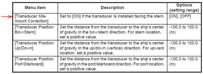
A couple of things to check here. First is the transducer pointed forward, as the B54 can fit either way in the fairing. If the transducer is backwards the error correction is doubled. If the transducer is in backwards there is a setting (Transducer Mis-Mount) in the transducer set up menu that you can check. Also make sure your +/- are correct in the XYZ offsets.

Snips
 
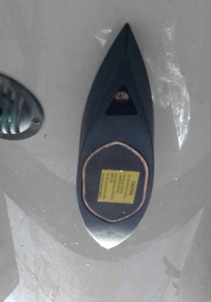
Can you tell by this photo? The anti-rotation pin is in the bow direction. Does the orientation of the warning label or the "dot" to the rear right side (in the photo) verify the orientation?
 

Attachments

  • B54.jpg
    B54.jpg
    74.2 KB · Views: 2,105
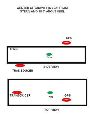
The transducer location is:
- on the center line of the boat
- to the stern and below the cog
- to the stern, below and in the port direction from the gps

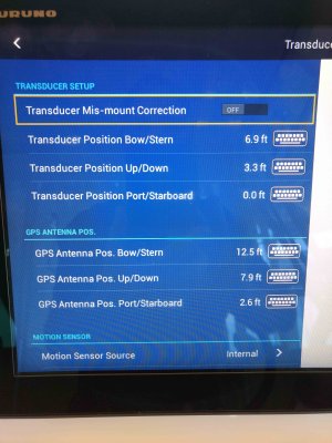
The transducer positions are set as:
6.9' bow/stern
3.3' up/down (should this be -)
0' port/stbd

GPS sensor position is set as:
12.5' bow/stern
7.9' up/down (should this be -)
2.6' port/stbd

(the wording describing +/- sign is confusing to me, the words change from "location" to "direction" in determining the sign of the value)

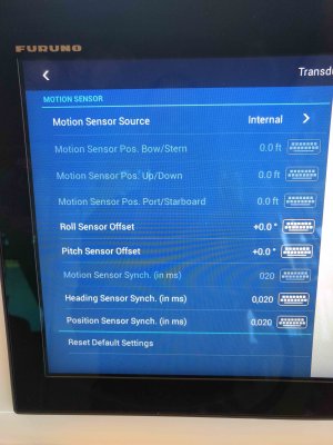
I am using the internal motion sensor.

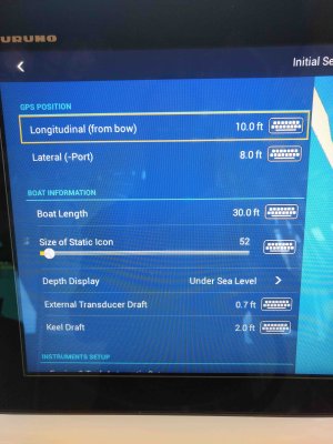
Attached are photos of the setup screens. Please advise if you see any issues.
Thank you
 

Attachments

  • DFF3D setup 1.jpg
    DFF3D setup 1.jpg
    853 KB · Views: 2,103
  • DFF3D setup 2.jpg
    DFF3D setup 2.jpg
    832 KB · Views: 2,103
  • DFF3D setup3.jpg
    DFF3D setup3.jpg
    862.6 KB · Views: 2,103
Flowmotion,
Thanks for the additional information. By looking at the dot (temp sensor) I can tell your your transducer is pointed forward (I trust you removed that yellow sticker). I can't tell how many times I have tripped myself up with these +/- also. The first challenge on smaller vessels trying "pick" the CG as most won't have a stability report to go by. Here assume a mid-ship point (port/stbd) and do the best you can (for/aft) taking into account engines, fuel/water tanks, etc.. The height of the CG will be slightly above the water line. Both the GPS and Transducer locations are in reference to the vessel's CG so looking at your data this is what I came up with.
Your transducer is behind and above the CG.
The GPS antenna is behind, above and to the port side.
So at least the transducer position should be a minus instead of a positive.

Snips
 
Snips,
The boat manufacturer gave me the CG. The boat is 31' long. The CG is 122" from the stern and 38.5" above the transom/keel intersection.

Since the transducer is mounted on the keel I would call it below the CG. Does that mean I need to make that number "-"?

My gps antenna is on the stbd side of the boat and in front of the transducer. As you stated it is on the port side and behind the transducer. Does that mean I need "-" values for those items also?

I am confused by your statement that the gps location is relative to the CG. The manual references the relative position of the gps to the transducer, not the CG. Is the manual wrong?

I appreciate your help on this...I am lost with the manual.
 
Flowmotion,
You are correct, the manual indicates Transducer to GPS. I am currently debating this point with Japan. However either way if the GPS is forward/starboard it should be minus/minus instead of plus/plus.

Snips
 
Thank you...that should help. Can we close the loop? Are the values (+/-) now correct?

The transducer positions are set as:
+6.9' bow/stern
-3.3' up/down
0' port/stbd

GPS sensor position is set as:
- 12.5' bow/stern
+7.9' up/down
- 2.6' port/stbd
 
Flowmotion,
Those will be better.

Transducer to CG
Stern +6.9
Down -3.3

GPS to Transducer
Bow -12.5
Up +7.9
Starboard -2.6

The only variable now will be the where the GPS to measured to i.e the Transducer or CG. I would very interested to hear what works better of your installation.

Snips
 
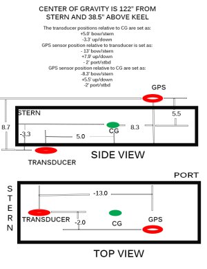
I will try the values as indicated in the attached that we agreed on.

If they are correct the manual must be changed. For instance, on page 3-6 it shows an up arrow on the transducer toward the GG with the statement "Up dir.:"+"". However, you are indicating it should be a "-" value for a transducer below the CG. Very confusing.

Thank you for the quick responses.
 

Attachments

  • DFF3D drawing.jpg
    DFF3D drawing.jpg
    84 KB · Views: 1,620
Flowmotion,
It hard for me to tell much without seeing the water conditions also.
So are you seeing any improve? the same? or worse?

Snips
 
I agree...hard to tell.
I need to wait for a day with more waves.

Meanwhile, I remeasured the distances and have two sets, one with transducer to gps distances and the other with cg to gps distances. I will try both and see if one is better than the other.

It will be a few weeks before I can provide an update.

Do the monitor numbers look generally ok?
 
I was able to try new settings today. As per our discussion, one set of parameters is based on the manual, i.e using gps to transducer distances. The other set of parameters is based on gps to center of gravity measurements, as you suggested.

The links below are to the videos. Neither setting renders the cross section display rock solid. It still moves with boat movement. Is there any way one can look at the behavior of the cross section and determine which setup parameters should be changed and in what direction?

gps to transducer: https://youtu.be/NY4-KicFe70
gps to cog: https://youtu.be/VNoITzqyUiU
 

Attachments

  • DFF3D new parameters.jpg
    DFF3D new parameters.jpg
    125 KB · Views: 1,451
flowmotion,
After numerous emails with Japan they are sticking with measuring everything from the transducer to the GPS antenna. So forward is minus, up is plus and starboard is minus.
I would curious if you unplug the motion sensor do you see any difference and when you have the sensor plugged in what checking the mis-match box does.

Snips
 
Snips,
The motion sensor is the transducer internal one so I can't disable it. Would it be useful to set the motion sensor as external as I do not have an external motion sensor? Would be that the same as disconnecting it?

I provided the results of settings done both ways: gps relative to transducer and gps relative to cog. Do you see any differences between the two?

Has anyone using the DFF-3D been able to demonstrate motion compensation with the internal transducer motion sensor? Is my performance the best I can expect?

Do you have any suggestions of changing one or more settings to see if the compensation improves?

I am not sure what you mean by the mismatch box? Which setting is that?

Finally, there are three settings I have not entered: roll sensor offset, pitch sensor offset, and motion sensor time lag. Do I need to adjust any of these when using the 165T-B54 transducer?
 
Flowmotion,
The motion sensor has a plug on it so it can be easily disconnected. The transducer Mis-mount is the top item in the transducer menu. Also you shouldn't be able to enter a lag offset when the transducer is selected as the motion sensor. However if you are able to get into this menu the delay should be 0.

Snips
 

Attachments

  • Xducer.JPG
    Xducer.JPG
    82.6 KB · Views: 1,430
Back
Top