A
Anonymous
Guest
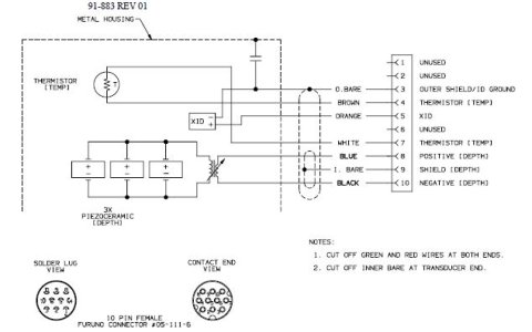
Hello, I am new to this forum and hoping someone could help. I recently installed a Furuno VX2 unit (RDP 149) the network sounder DFF1, the MB-1100 matching box to go along with the Furuno Xducer 526 TID-LTD/20. After getting all this installed, I'm not getting any signal to my display. I have heard conflicting information about needing the Matching Box MB-1100. To fix my problem, I have heard that I need to bypass the MB-1100 and pig tail the 10 pin connector from my transducer straight to the DFF1. I haven't tried that yet. I did hear that by doing this, I would only be getting 600w out of my transducer instead of 1000w. Does the MB-1100 boost the wattage from 600w to 1000w? Also, I would think that I should be getting some clicking out of my transducer out of the water, but I'm not hearing anything. This makes me think the wiring is not right. Attached is the wiring from the transducer to the MB-1100. That is the red wire in the top terminal.

Also. I don't like how the temp wires have nothing to connect to. How do I get temp? My switches on the DFF1 are 1 and 4 are on, and 2 and 3 are off per the instructions. Please help me with any information. I have limited Furuno resources where I live in Hawaii. Thank you!
Also. I don't like how the temp wires have nothing to connect to. How do I get temp? My switches on the DFF1 are 1 and 4 are on, and 2 and 3 are off per the instructions. Please help me with any information. I have limited Furuno resources where I live in Hawaii. Thank you!