You are using an out of date browser. It may not display this or other websites correctly.
You should upgrade or use an alternative browser.
You should upgrade or use an alternative browser.
wiring rudder reference unit FAP-6112
- Thread starter Arjen
- Start date
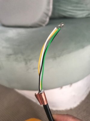
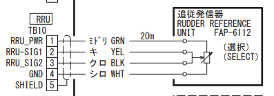
The cable going to the RRU has the enclosed colors but the outer covering is a braided shield wire. You would take that "Shield" and put it into pin 5 of TB10. If you really want to be neat, you could take a short wire (maybe blue wire so it doesn't match the others) and solder it to the cable shield then put the other end of the short wire into Pin5 of the TB10 Wago connection. You will see the shield under that copper tape.
thank you for your clear explanation!The cable going to the RRU has the enclosed colors but the outer covering is a braided shield wire. You would take that "Shield" and put it into pin 5 of TB10. If you really want to be neat, you could take a short wire (maybe blue wire so it doesn't match the others) and solder it to the cable shield then put the other end of the short wire into Pin5 of the TB10 Wago connection. You will see the shield under that copper tape.
In addition.. Is it correct that for all the cables connected to the 7002, the shield must "touch" the earth terminal? Using alu foil around the cable wires?
No, unless the interconnection drawing shows it going to frame ground (FG) it should not ground out to the case. Doing so would be a very good method to create grounding loops and possible problems.
ok thank youNo, unless the interconnection drawing shows it going to frame ground (FG) it should not ground out to the case. Doing so would be a very good method to create grounding loops and possible problems.
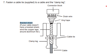
I am confused by the drawing in the manual - 2.2.2. how to fasten cables to the cable clamps-
The aluminium foil connects to the clamp leg (which is connected to the ground) and the shield wire is connected to the aluminium foil.

While what is shown makes connection to the case, it also needs to make connection to pin 5 (as the interconnection shows). Using a short piece of wire soldered to the braided shield with the other end of that wire being put into the connector. The drawing is showing that it is also going to the frame ground, that is all. In some connections having it touch the frame like the NMEA 2000 connection can cause a grounding loop. In this case per the manual the engineers want this to the frame. When in doubt follow the book.
Thank you Johnny,While what is shown makes connection to the case, it also needs to make connection to pin 5 (as the interconnection shows). Using a short piece of wire soldered to the braided shield with the other end of that wire being put into the connector. The drawing is showing that it is also going to the frame ground, that is all. In some connections having it touch the frame like the NMEA 2000 connection can cause a grounding loop. In this case per the manual the engineers want this to the frame. When in doubt follow the book.
Hopefully I will get it all working soon!
This weekend I got the system working.. All looks good. Waiting for good weather to do the seatrial.
The only thing that doesn't work is the nmea 2000 data on the FAP-7001
It does display the connected devices in the can bus devicelist
But no incoming data, highlighted pgn numbers.
The FAP-711C is working fine with all nescesarry data displayed
First thing what crossed my mind , is a 14year old FAP-7001 compatible with the setup below?
(Purchased in 2022..)
I tried several combinations. As standalone unit and also directly connected to the fap-711C but nothing seems to make a difference (terminators are on the control units)
It does show the rudder position and I can change course and choose for auto or stb
Hopefully someone has an idea what to do next?
Thank you in advance
set up:
50ST203
FAP-7002
FAP-6112
PG-700
Helm:
NAV pilot 711C
2x FI-70
Charttable:
FI-70
FI-50 (not connected yet)
FAP-7001
If you have an older pilot processor the first step would be to update the software to get it currently. Please understand the Navpilot 711c control heads are not NMEA 2000 and how it connects and terminates is totally unrelated to the 2000 bus. If you provide a drawing of the system it would be easier to provide guidance.
ok, I will figure out the update..
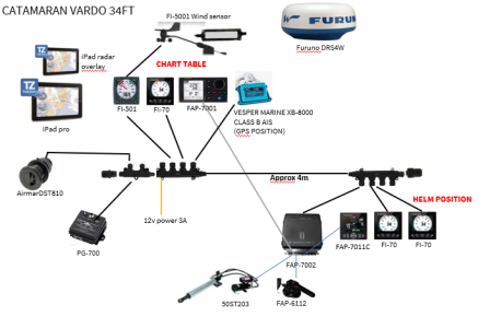
I have not a "technical"drawing but the drawing below I used when I purchased the materials.
So hopefully it is good enough..
It's pretty straightforward as we don't use a plotter. Navigation with an iPad.
At the moment I use the gps position from the nmea of a horizon vhf radio.
It appears on the device list of both control units. But also on de 711C it doesn't display the data...
The pg-700 does work on the 711C and therefor I can control the rudder in stb and auto mode...

Ensure the termination button on the PG700 is OFF.
Because you have two pilot control heads both wired directly to the pilot (Using channel A&B) the jumper setting J104 should be verified that it is setup for 3-4 and not 1-2.
Because you have two pilot control heads both wired directly to the pilot (Using channel A&B) the jumper setting J104 should be verified that it is setup for 3-4 and not 1-2.
yes , did both indeedEnsure the termination button on the PG700 is OFF.
Because you have two pilot control heads both wired directly to the pilot (Using channel A&B) the jumper setting J104 should be verified that it is setup for 3-4 and not 1-2.
Is there something I have to do in the can bus port setup for the gps data to display ? or data source setup?
The set up of the pilot has to be done where the data sources have been selected. It will not display a source of data which hasn't been properly selected in the data sources.
all is working on the 711c now
I had to select the nmea output on the vhf radio for gps position
For the moment it means I can control the autopilot also inside on the 7001 but will display the course on the FI-70
(untill I tried the software update)
Last question Is there anything I have to do with the output pgn list? everything is now on OFF
Thank you so far!
I had to select the nmea output on the vhf radio for gps position
For the moment it means I can control the autopilot also inside on the 7001 but will display the course on the FI-70
(untill I tried the software update)
Last question
Thank you so far!
Leave PGNs off unless you know it is something that is needed to the bus. You don't want to create unnecessary bus traffic. About the only items we would normally turn on from the pilot processor is RUDDER information so that it can be seen by other devices like the FI-70.
Leave PGNs off unless you know it is something that is needed to the bus. You don't want to create unnecessary bus traffic. About the only items we would normally turn on from the pilot processor is RUDDER information so that it can be seen by other devices like the FI-70.
Similar threads
- Replies
- 4
- Views
- 688
- Replies
- 9
- Views
- 941


