NavNet3D, N2000 Heading Sensor not recognized

jimb

New member
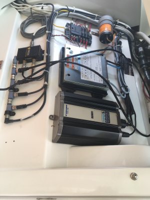
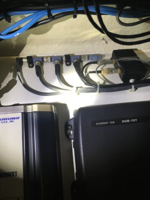
I have an older (but new to me) NavNet 3D MFD12 system, and am trying to add an NMEA2000 heading sensor. Unfortunately I don't have a wiring diagram for the system, but the N2000 backbone is obvious (see attached photo). So I inserted a new T connected to the new heading sensor before the terminating resistor, reconnected the terminating. resistor, ran the Install Wizard, but the heading sensor is not recognized.

I don't yet know what is connected to that 'backbone', and as the cables are all tightly bundled, I'm reluctant at this point to cut everything open & go exploring.

My system is
Furuno MFD12 Navnet 3D Version: 1950055-02.11
Hub 101 (ethernet hub)
FI-503 Depth/Speed/Temp display (connected directly to N2000 on the MFD12)
DT-800PSF Airmar depth/temp sensor (shows up as DT-200 in MFD12)
GP-330B GPS Receiver (connected via DRS on mast) - new updated version to fix date issue.
DRS - Radome (probably DRS4D, 24", 9410MHz, 4kW)
BBWX-1 Sirius Weather (not subscribed, is connected & powered)

I attached a photo of the N2000 backbone, which is where I tried adding the heading sensor.

Since the FI-503 is connected directly to the MFD12, maybe I'm supposed to add the heading sensor there instead?

The heading sensor I'm using is just an inexpensive Garmin Steadycast for testing purposes. I understand the limitations of that sensor, but It does output 127250, and should be able to be recognized.

Any suggestions would be welcome. Thanks!
IMG_4982 copy.JPG
 
If it does output 127250, I would expect it to been seen on the network. I see only one bus terminator on the network but hopefully you have another that isn't shown. I don't seem to find that device as certified at NMEA.ORG.
https://www.nmea.org/content/STANDARDS/ ... d_products
If not certified, it might have sentence error that keeps it from being seen but not sure. Do you have a NMEA 2000 recording of the data being provided? I am sure our support guys would be willing to test it at our service center to find out if there is a compatibility issue.
 
I finally got the unit to pull up on NMEA.ORG. Researching we had another customer try to use one of these with the NN3D. They had problems because the compass PGN had variation data that was invalid. I never heard if they got it working but they provided a screenshot of the transmitted PGNs from the NMEA 2000 port monitor. If the data is correct it should work. You might check to see if the device shows up in the NN3D wizard under the GLOBAL - NICKNAME tab and provide it a nickname if it doesn't have one. Then you should be able to select it as the heading source under GLOBAL - DATA SOURCES.
 
Thanks for the research & suggestions. I didn't look at the Nicknames section. It didn't show up as an option in Global/Heading. The only thing available was DT200, which is the depth sensor. I'll take a look & see what I can find.
 
Johnny,

I connected the heading sensor again & tried going into the Port Monitor in the Install Wizard, and it did show up there, but as node '0'. I've also attached a better photo of the network layout, and my current understanding of what's connected to what.

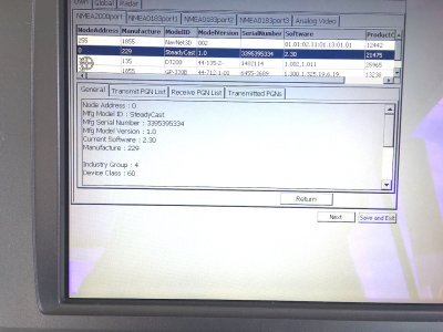
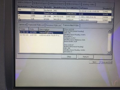
Photo 5283 - Is from Port Monitor in Install Wizard. It shows SteadyCast as node '0', which is probably why it isn't showing up in the MFD. That doesn't sound like a valid node. The Port Monitor does show that it's sending 127250 repeatedly though.

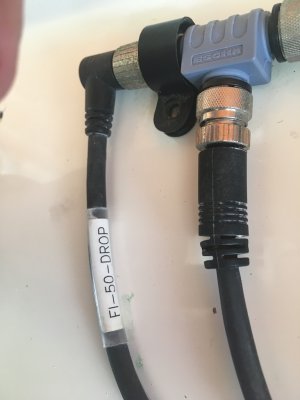
Photo 5295 - Shows the network layout. In the N2K 'backbone', SteadyCast is the last T before the terminating resistor. The right angle connector cable says FI-50-DROP (photo 5298), but it's not connected to the FI-503. The FI-503 is connected directly to the MFD12 NMEA2000 connector, and is the only thing connected there. I am guessing that the right angle connector is connected to the N2K wires in the MFD12 Data2 pigtail (haven't uncovered that yet), and I assume it's terminated in the MFD12. I don't know what the other three N2K drops are for. The only other N2K thing that's unaccounted for is the depth sensor. Leaving two drops unknown at present. I believe my PG-330B is connected by N2K to the Radar, which is then connected to the Hub101 by Ethernet.

The MFD12, and (I believe) Sirius Weather & Radar are connected to Hub101 by Ethernet.

Any suggestions welcome. Thanks again for your help. This is not time critical.

Thanks,
Jim

IMG_5283 copy.JPG

IMG_5295 copy.JPG

IMG_5298 copy.JPG
 
Further to the last post, I was looking at the MFD12 schematic & see that Data 2 does not have N2K on it. I thought it did. So, my assumption that the N2K 'backbone' was connected there is apparently wrong. So, I'm not sure what it's connected to. May have to start taking things apart... We're the 3rd owner of this boat, so who knows what's been done. Unfortunate, because other than the heading sensor test, it seems to be working fine.
 
Yes, it important to sketch out the network and ensure all the needs are met. I only see one termination resistor and it is VERY important that the bus have two terminations. I don't really have a concern about the node address 0. If you unplugged it and power the 2000 then plug it in, the node address would be diffrent. I would be more concerned with what the raw data it is providing by the PGN. The last SteadyCast case I worked the PGN data was wrong due to the device putting out an excessive variation value. Try to get a screen capture of the heading data in the NN3D NMEA 2000 port monitor of the SteadyCast PGN information.
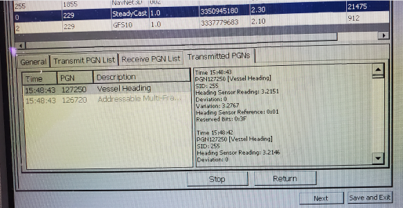
Here is a a shot of the other case where the data provided was wrong and rejected by the NN3D. Crapcast.png In this case the angle such as heading in the port monitor is shown at radian (rad).

Heading Sensor Reading: 3.2151 rad ≒184.211... degrees
Variation: 3.2767 rad ≒187.741... degrees

Because the heading data on the Port Monitor has invalid variation data, the NN3D won't use it. Maybe it is the same with your case.
 
I checked the port monitor with the SteadyCast attached, then followed the calibration instructions (unplug from network, plug back in, rotate through 360 degrees twice, confirm it's not transmitting heading PGN (it wasn't), rotate through 360 degrees 1.5 more times, confirm it's now transmitting heading PGN - it was). The heading reading was 4.0471 radians, or 231.88 degrees, which agrees with my magnetic compass. However, like your example, it was showing a variation of 3.2767 radians, or 187.74 degrees. No idea where it's getting that from. Our local variation is ~+12 degrees. I don't know how it would calculate that anyway. I doubt it has a global database. Interestingly, that variation stays fixed, even when, prior to calibrating, the sensor was showing a different heading. Anyway, as you predicted, NN3D ignores both the heading & the variation. Screenshot attached.

I'll have to get into the N2K network when I have a chance. I tried disconnecting each branch one at a time to see what happens. From resistor towards the right angle connector: 1st branch: no change, 2nd & 3rd branch: FI-503 goes dead (even though it's also connected directly to the MFD's N2K connector); 4th branch: MFD12 appears to lose position updates. Despite this it seems to work.

Thanks again for all your help.

IMG_5302 copy.JPG
 
You might reach out to the company to see if there is newer software to fix the variation infomation. It will be rejected if not valid info so I am guessing the heading not working isn't related to the bus.
 
Adding a tee on the end, moving the terminator to it, and connecting the Steadycast on the tee center port is the right process. Calibrating it is probably important, so ask the vendor for more info about that. Note that heading and compass units are usually very picky about where you place them. As in, not near magnets (like speakers) or large pieces of ferrous metal.

Two questions, how is your N2K network connected to the MFD12? You mention having the FI503 display "connected directly". Then how are the other N2K devices linked? I question the accuracy of the FI503 being the only thing connected to the N2K port on the MFD12.

Second, that drop cable on the end tee.. where is it going? Because the end of a tee is supposed to go to either another tee or have a terminator in it. Not as a drop to a device.

You should have only one device connected to each tee center connection, and only cables or terminators at the ends. Each device should only be connected to the center port on a tee, not to an end.
 
Back
Top