DRS4D-NXT Wiring Question

MarMax

Furuno Super Fan
I'm about to order a DRS4D-NXT to replace my DRS4D and can't seem to glean enough from the installation manual to figure out my wiring options. Currently my GP330B is connected to the DRS4D and with the NXT upgrade I'll be connecting the GP330B directly to the N2K network (something I've wanted to do regardless).

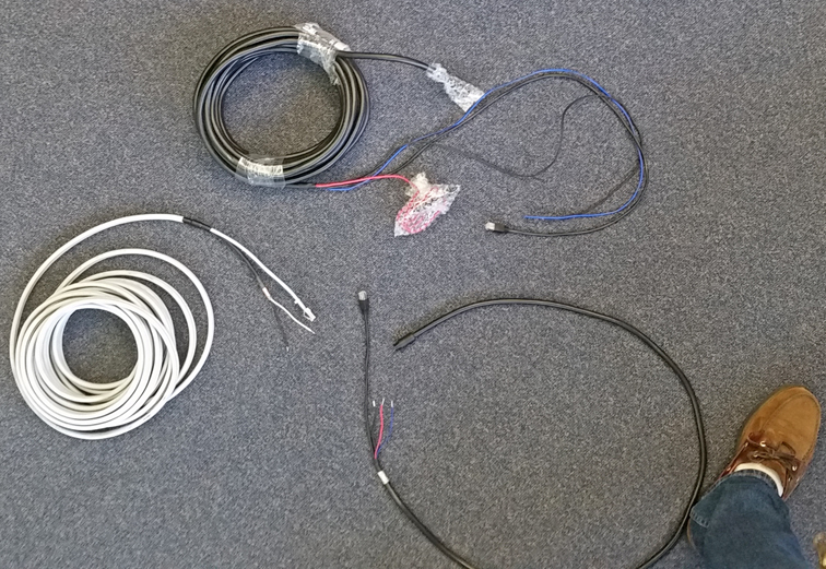
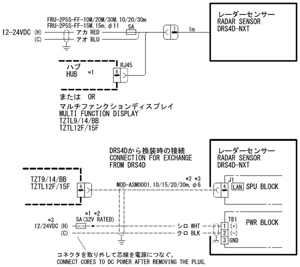
Since I need to pull cables the plan is to remove the existing DRS4D signal/power cable and use the 001-376-480-00 cable that comes with the NXT. I'd like to shorten this cable but it looks like there are connectors on both ends. It's hard to tell from the photos online and the installation instructions, but it looks like the NXT has a short pigtail to a connector and this is where the 15M (001-376-480-00) cable attaches.

In the installation manual there is also a method shown to use the existing DRS4D cable which looks like the pigtail is not used and wiring is done inside the NXT. So my question is if can I take the cover off the NXT and remove the pigtail, then cut the NXT connector end off the 001-376-480-00 to the length I need and directly wire to the NXT? This would leave the RJ45 end and power wires untouched. Please let me know if I'm on track here. Thanks.

NXT_ConnectionDiagramS.jpg
 
It would work best if you use your existing DRS cable. You would remove the pigtail cable that comes with the DRS4D-NXT and run your existing cable into the new unit. Inside there is an RJ45 port and power connection to connect the older wiring. (This is where the pigtail currently connects in the NXT). This saves you from pulling wire in your retrofit. You might even be able to get the dealer to buy the unused scanner cable back from you as part of the deal.
 
Thank you Johnny. It sounds like there is a terminal block so that the pigtail can be removed and wiring can be done directly. My plan is to sell the DRS4D, PSU017 and cables. The GP330B has to be moved to the N2K network so I have to remove and replace all the cables anyway.

The existing DRS cable is a double and looks to be bigger than the new NXT cable so hopefully I'll end up with a bit less cable area overall even though there will still be two cables (NXT and N2K).

Unless I missed something it sounds like cutting the NXT cable at the pigtail connection end, removing the pigtail from the NXT and then wiring directly to the terminal block is acceptable. I will need a detailed NXT cable and terminal block wiring diagram. Is this in the online materials somewhere or available upon request?
 
There is no terminal block option offered by Furuno but many install their own for where they have a mast that comes down etc. There is no problem as long as you match up the wiring correctly. If you are not going to try to use your existing cable, then why do you want to remove the pigtail from the NXT?
 
Johnny, I'm really glad you asked another question. It got me thinking and I'll have a lot more re-wiring to do than I anticipated. I can see why there is an option to utilize the DRS cable in-lieu of the pigtail. My hub is located in a different place than the radar power so re-using the DRS cable will allow me to leave the ethernet cable run to the hub as-is.

I'll still need to run an N2K cable up to the radome/gps mount for the GP330B. As you can see from the photo I've been running the GP330B to the DRS. I'll need to remove the black GPS cable (kinda hidden behind the DRS cable) and also get a rubber stopper with two holes instead of three. Hopefully there was a two-hole stopper shipped with the DRS and I'll be able to find it somewhere.

My comments relative to the "terminal block" were referring to the wiring inside the DRS or NXT. Is there a detailed diagram that shows exactly which colored wires go where inside the radome? Kinda like the instructions for the DFF3D.

DRS4D_3pmS.jpg
 
Johnny, I'm bumping this up to get an answer to my question regarding how the pigtail is wired inside the NXT. Is there an RJ45 plug inside the NXT for the ethernet connection or does the pigtail do everything? I only have room to pass cable only up to the radome and I'll need to remove the DRS cable to provide room for the NXT cable and N2K cable for the GPS. But I still need to know how to connect the wires at the NXT since I have to cut the connector off to run the cable and will need the wiring diagram for the pigtail inside the NXT.

Hope this makes sense.
 
Attached is a document I put together for you. It shows you how the internal pigtail is inside the NXT dome. It has an RJ45 and power wires just like the older style cable but then blend into one cable and goes out the unit via the cable gland. Normally someone retrofitting like yourself would just disconnect the power wires of the pigtail and the RJ45, and then open the cable gland; removing the entire pigtail. You would then use the old cable and its cable gland and bring the older cable directly into the unit, connect the RJ45 into the RJ45 port, remove the small power connector used on the DRS4D and put the power wires into the DRS4D power clamp connector. Done and done.
View attachment Internal view of DRS4DNXT.pdf
 
I was able to get a picture of the cables, the original DRS cable, the pigtail and the drop for the NXT. Thought I'd post it up here in case anyone else is curious. Just right-click on the image and open in a new tab for full size. Has my shoe in the pic for reference . . lol, shoe is 12" long. Light colored cable is the DRS.

NXTnDRS_CablesS.jpg
 
I opened up the DRS4D-NXT and looked at the RJ45 Ethernet connector on the radar end, and the wiring is as follows:

PIN
1 White/Orange
2 Orange
3 White/Blue
6 Blue

Could someone please confirm whether the pin outs on either end (radar and display) are exactly the same or different?

The connector on my MFD/display end somehow came off, so I can't confirm.
 
Back
Top