Radar scanner unit RSB-0036

flytech

New member
Good morning to all members of the forum,
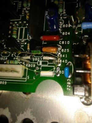
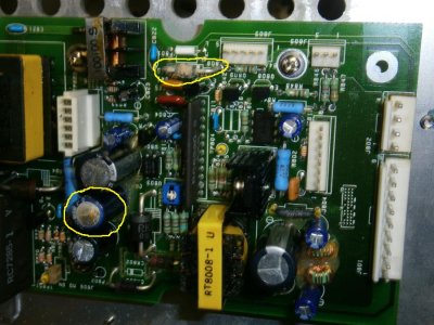
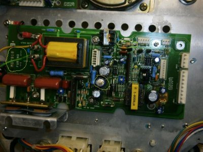
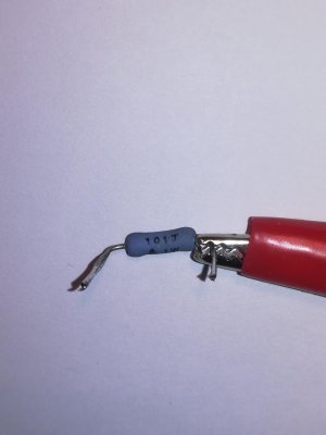
I'm a new member, my name is Mauro and I’m writing from Italy, I’m an passionate of electronics and radars. For this I bought a radar Furuno, FCP-1040 ( display 1830 and scanner antenna RSB-0036 serial number 2358-corrosion..last number is..3). In the RF chassis there is the card “Modulator MD-7918” with some components damage, a condensator 2.2microFarad 450V and a diode. This diode,CR808, is broken because of its corrosion it isn’t possible to indentify it and I haven’t got the main board MD-7918’s electronic scheme .
I ask kindly if you can tell me what kind of diode it is and again I ask you if I ca n have the main board MD-7918’s electronic scheme.
Eventually could be provide a new main board?

Thank you for your kindness and patience.

Best regard
Mauro
 

Attachments

  • diode1.jpg
    diode1.jpg
    86.1 KB · Views: 3,703
  • diode2.jpg
    diode2.jpg
    195.7 KB · Views: 3,703
  • board MD-7918.jpg
    board MD-7918.jpg
    174.4 KB · Views: 3,703
The 1830 is a very old radar (22 to 25 years old) and I am sorry to say the Modulator board is no longer available for sale.

The Service Manual of the time doesn't address the value of CR808 or include any schematic of that board. Furuno no longer provides schematics to distributors or dealers due to patent infringements.

You might contact your distributor to see if they can offer any assistance.

FURUNO ITALIA S.R.L.Via Ottorino Respighi, 29 - 47043 Gatteo (FC), ItalyPhone +39 0541 1849400Fax +39 0541 1849410E-mail sales@furuno.it (Sales)E-mail service@furuno.it (Service)
 
hi mauro
my name is tim and I have the same problem. did you manage to find a number for CR808 if so please let me know.
regards
tim
 
Hi Tim,
sorry for the delay in the reply, but I only visited the forum now after a long time. The original CR808 diode is a GP30D made by Texas Instrument, unfortunately it seems to be an obsolete component. From the information I gathered, the builder Vishay builds a diode with the same characteristics.

Best regards
Mauro
 
Hi Mauro,

I know this is an old thread but here's hoping.

I also have a damaged 1830 radar with a component whose value that I can't identify. It is R829 on the attached copy of your original photo on the MD7918 Modulator Board (marked in red) and tucked in awkwardly between the driver transformer for the magnatron and TP803 (6-way white female connector).

Furuno MD-7918.jpg

In the unlikely chance that you or others still has this model and has the top off the scanner can you identify this resistor for me? It's a 1 watt wire-wound (from others related nearby) but is burnt out and open circuit, so no visible markings. Given its tight position it may not be legible on a working board, but an in-circuit multi-meter reading on ohms scale would help. It won't be more than 470 ohms and maybe half that.

I have traced and drawn the associated circuit and understand its function. The driver FETs (Q805 and Q806) were blown (replaced) and the clamping/flyback diode CR804 (replaced) so this is one component away from a working set again. R829 is the limiter for the charge circuits of the two capacitors C816 and C817 that drive the EHT for the magnatron anode.

Always the optimist - thank you!
 
Hi Neil,
I am glad that you have written to me and I am sorry for the late answer but I have been busy. I still have this model of radar (1830 and RSB0036 scanner antenna). In my free time I am fixing the scanner antenna. I have worked on the MD7918 Modulator Board; I have replaced defective capacitors but while testing it, on the display appears the message “ BP SIG MISSING” and the antenna engine doesn’t work. As soon as I can, I will carry on with the tests.
I have another MD7918 Modulator Board from which I take changing components. In the coming days, I will be able to go and check if the value of the resistor you ask for.
I will answer you as soon as I can.

Best regards,
Mauro
 
Hi Mauro,
Thanks so much for replying and great news that you are still active and still have the same set. And of course, when you get a chance, I will be more than grateful if you can identify the resistor for me.

For my part I will try to help you as much as I can. As Johnny (moderator) has said in this thread, there are no schematics of the circuit boards published for at the time of the 1830 release, it was covered by a USA patent (the FET front-end was a new concept). There is however, an Operator's manual which apart from operating and set-up instructions, does show the main cable pin-outs and the interconnecting pin-outs for the Modulator and IF boards in the scanner unit. I have a scanned copy of this (.pdf) that I can post here or mail you, but it is available on a number of locations if you search for 'Furuno Operator's Manual Model 1830'.

Forgive me if you are well-versed in this, but the diode you replaced CR808, is directly in the scanner motor control circuit and is connected to J802, pin 2 which is labelled Motor(+) - part of the cable between display and scanner - and J803 pins 1 and 4, both labelled +12v which is the connector for the antenna motor. The other end of CR808 goes to Ground, so my guess is this is a clamping diode to kill any fly-back from the inductive load of the motor. If that had blown or failed through corrosion, there could be other components damaged too.

The message 'BP Signal Missing' is 'Bearing Pulse' which is J802 pin 1 and is generated by the motor circuitry from the rotary 'Encoder' output from the motor (J803, pin 3). In this case, it probably just means that the antenna isn't rotating (as you have observed).

Forgive me again if this is basic and obvious, but there is a switch on the back of the display unit to disable the antenna rotation, but this must already be in the ON position now for the display thinks the antenna should be rotating. But it's worth a basic voltage check on the Modulator board J801 pins 1 and 2 (+12v) and pins 4 and 5 (-12v) and Ground on pin 3. Also check J802, pin 2 'Motor(+)'' which my guess is should be at +12v to activate the motor as it connects via the main cable to the power supply board in the display via the 'Scanner ON/OFF' switch to +12v on P1 pin 4 on the power supply board.

Be aware there are some very high voltages (High Tension) on this Modulator board: around 415v to 450v on the primary of magnetron driver transformer and substantially higher on the secondary (output) side TB801 and TB802 so take care!

When I get some time, I will try to trace the motor control circuitry that might help you to know why the motor isn't running.

Back to you soon,

Cheers,
Neil
 
Hi Neil,
thank you for the priceless advice you gave me in order to carry on with the research of the fault. As soon as the weather gets better , I will go on with the tests. I will surely keep you updated.
As to the resistor R829, its value is of 100 ohm- 1w. I enclose the photo of the component and the measure obtained with digital instrument . I am sorry if the answer is late but I have been busy with work.
If you have any question , don’t hesitate to ask.

bye
Mauro
 

Attachments

  • resistor 100_1W_1.jpg
    resistor 100_1W_1.jpg
    106 KB · Views: 1,673
  • resistor measurement.jpg
    resistor measurement.jpg
    254.4 KB · Views: 1,672
Mauro, I can't thank you enough for this especially for taking the time to remove and test the resistor - very much appreciated. And what is reassuring is that prior to finding your thread here, I had made the best calculation I could (based on the charge time of the RxC circuit and knowing the pulse rate published in the manual) and came up with 100 ohms so ordered an equivalent. I'll get it all back together in due course and let you know the result.

Just a quick update on your problem when you next get a chance to test again. In my previous post I mention the 'motor control circuit' only because the manual makes reference to such an item in some very basic troubleshooting notes. But looking on the board there isn't one other than the failed diode CR808! Just a +12v (and Ground) that originates on the power supply board, links to the scanner via the main cable and is routed on the Modulator board from the input (J802, pin 2) to the output to the motor on J803, pins 1 and 4. So as I said, a basic voltage test there is a good place to start.

Do get back to me when you are ready.

All the best,

Neil
 
I am trying to fix a Furuno 1941 Radar, this is an old radar and the modulator board MD7918 has some issues, but my biggest problem is that mostly all the markings on some of the components have been erased by age....I need to know the value of resistor R803. I think the driver transistors (Q805 & Q806) are defective and I will replace them. I would also like to know the resistance of the filament of the MSF 1422B magnetron.
 
Hi Barry,
sorry for the late reply, but I’m away from home for some days for work. As I come back, I’ll let you know about the information you asked for. Sorry but I ask you to be patient for a few more days.

Thank you
Mauro
 
Back
Top